


10
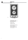
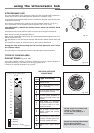
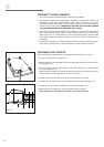
FASTENING THE COOKTOP
Each cooking hob is supplied with a set of tabs and screws fasten it on units.
✓ Cut the unit (as shown in the figure 4.1).
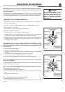
✓ Stretch gasket “D” over the edge of the hole made, being careful to overlay the junc-
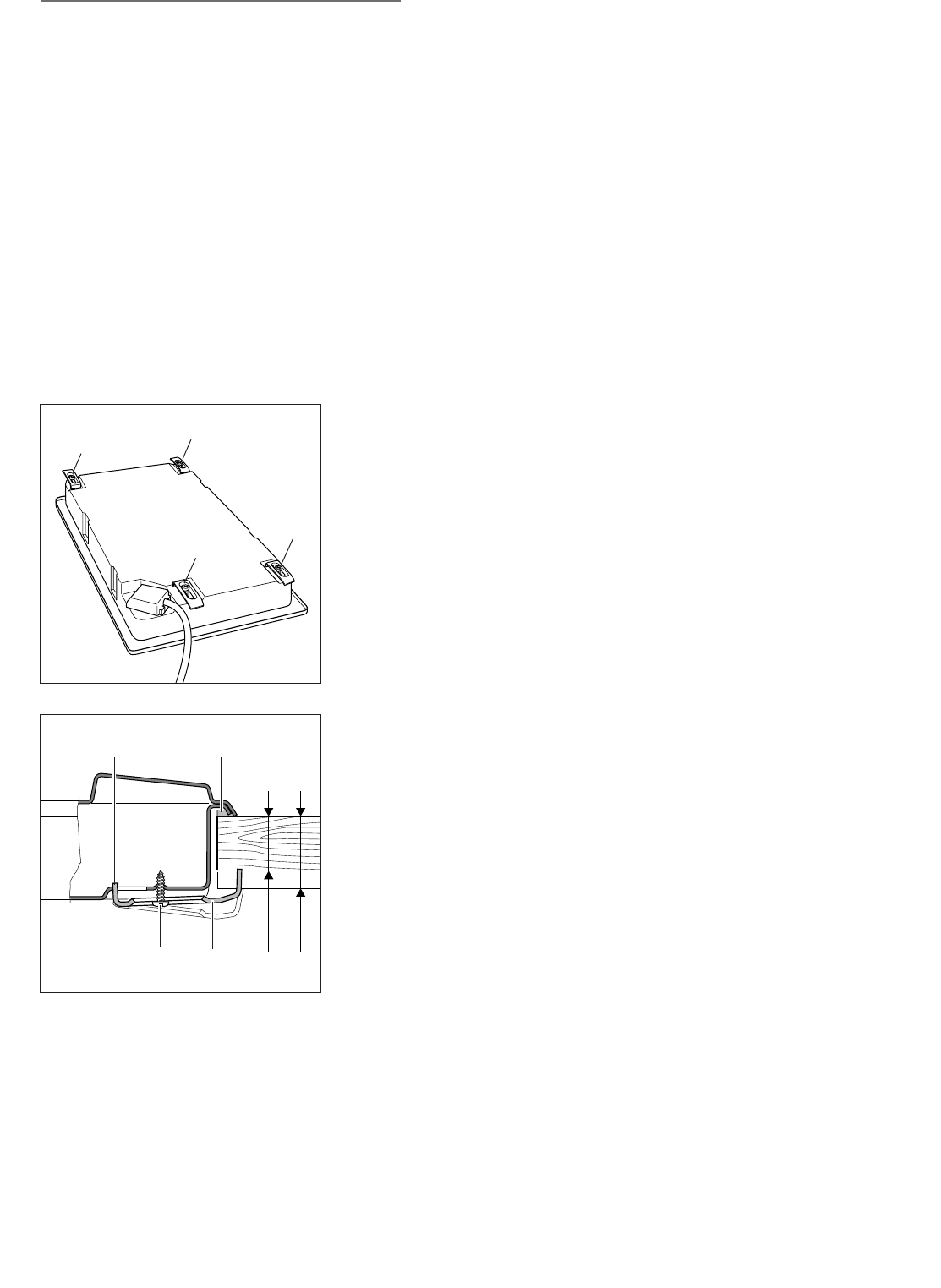
tion edges (fig. 4.4).
✓ Turn the cooking hob over and put tabs “A” into the mountings, only tighten screws
“B” a few turns (fig. 4.3).
Make sure that the tabs are mounted correctly as shown in the figures at the side.
Turn the tabs so that the cooktop can be put into the hole.
✓ Put the cooktop into the hole cut into the unit and position it correctly.
✓ Put tabs “A”; into place, tooth “C” of the tabs should go into the hole (fig. 4.4).
✓ Tighten screws “B” until the cooktop is completely secured (fig. 4.4).
✓ Remove the part of gasket “D” which protrudes from the cooktop.
Keep attention not to damage the cooktop or the cabinet surface.
A
A
A
A
Fig. 4.3
30 mm min.
40 mm max.
B
D
A
C
Fig. 4.4
ብ
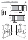
PROXIMITY TO SIDE CABINETS
1. The cooktop may be installed directly to existing base cabinets.
2. The cooktop CANNOT be installed directly adjacent to sidewalls, tall cabinets, tall
appliances, or other side vertical surfaces. There must be a minimum of 3” (76.2
mm) side clearance (left or right) from the cooktop cut-out to such combustible sur-
face above the counter heigh. IMPORTANT: ONE SIDE (LEFT OR RIGHT) ABOVE
THE COUNTER HEIGHT MUST AWAYS BE KEPT CLEAR.
3. The maximum upper cabinet depth recommended is 13” (330 mm). Wall cabinet
above the cooktop must be a minimum of 30” (762 mm) above the countertop for a
width of minimum 11” 13/32 (290 mm): it has to be centred with the cooktop. Side
wall cabinets above the cooktop must be a minimum of 18” (457 mm) above the
countertop.
4. If cabinet has a drawer, a 4” (102 mm) depth clearance from the top of the counter-
top to the top of the drawer (or other obstruction) in base cabinet is required.