


7
OVER OVEN INSTALLATION
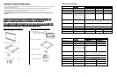
2” (5.1 cm) For 27” W. and 30” W. lower oven
4” (10.2 cm) For 36” W. lower oven
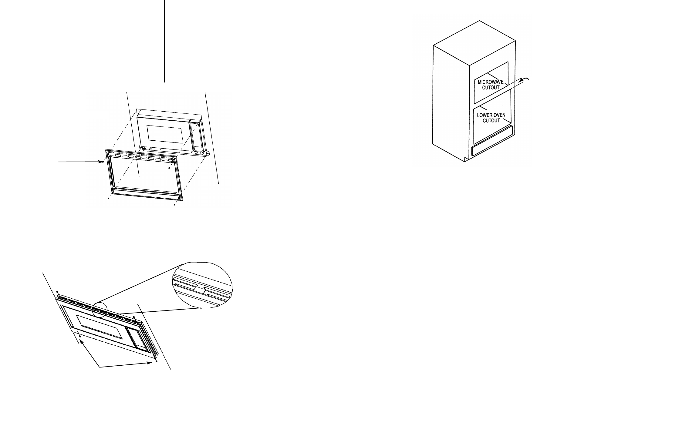
6
DMTK270 ONLY
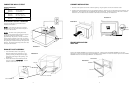
Position the BACK FRAME ASSEMBLY to be square with
the oven. Carefully place the BACK FRAME ASSEMBLY
on the oven. Check that the oven is level and secure the
lower portion FIRST with two of the Screw B. Adjusting
the BACK FRAME ASSEMBLY up or down may be
necessary in order to locate the thru holes on the exhaust
duct assembly. Secure the upper portion of the BACK
FRAME ASSEMBLY with the remaining Screw B. See
Illustration 5
DMTK300 ONLY
Position the BACK FRAME ASSEMBLY to be square with
the oven. Carefully place the BACK FRAME ASSEMBLY
on the oven. Check that the oven is level and secure the
upper portion FIRST with two of the Screw B. Secure the
bottom portion of the BACK FRAME ASSEMBLY with the
remaining two Screws B. See Illustration 5
Screw B
Illustration 5
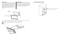
Place the FRONT FRAME ASSEMBLY through the microwave onto the BACK FRAME ASSEMBLY. Secure the FRONT
FRAME ASSEMBLY to the BACK FRAME ASSEMBLY with Screws C. See Illustration 6
NOTE: The center tab denotes correct orientation of the FRONT FRAME. See Detail B.
Illustration 6
Screw C
Detail B