


3130
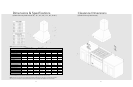
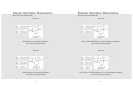
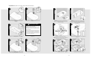
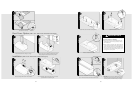
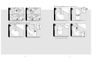
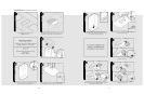
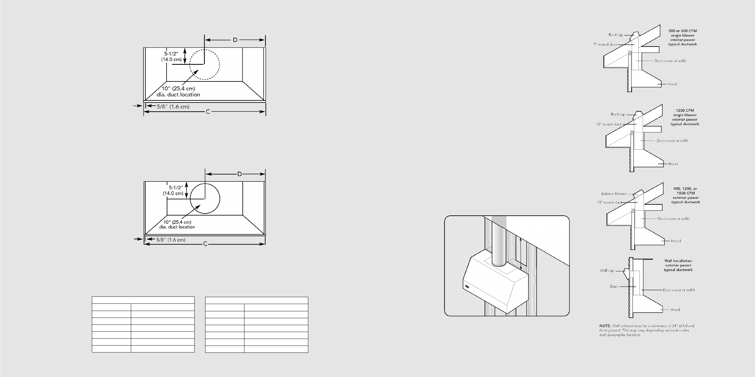
1200 or 1500 CFM Exterior or In-Line Ventilator Installation
48”, 54”, 60”, 66” W. Models
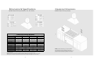
1200 CFM Interior Ventilator Installation
30”, 36”, 42”, 48”, 54”, 60”, 66” W. Models
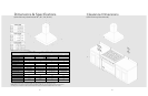
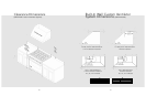
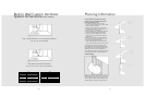
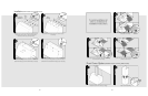
Built-In Wall Custom Ventilator
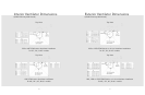
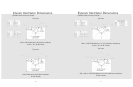
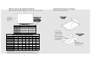
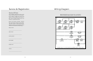
System Dimensions (VBCV Models)
C
30” W. 28-1/4” (71.8 cm)
36” W. 34-1/4” (87.0 cm)
42” W. 40-1/4” (102.2 cm)
48” W. 46-1/4” (117.5 cm)
54” W. 52-1/4” (132.7 cm)
60” W. 58-1/4” (148.0 cm)
66” W. 64-1/4” (163.2 cm)
D
30” W. 14-1/8” (35.9 cm)
36” W. 17-1/8” (43.5 cm)
42” W. 20-1/8” (51.1 cm)
48” W. 23-1/8” (58.7 cm)
54” W. 26-1/8” (66.4 cm)
60” W. 29-1/8” (74.0 cm)
66” W. 32-1/8” (81.6 cm)
Planning Information
Proper installation of ducting is extremely
important to ensure maximum performance
from any ventilation product.
• All CFMs are based on tests at 0.1 static
pressure: without applying static pressure, CFM
would be greatly overstated.
• Straight runs and gradual turns are best; for
example, each 90º elbow is equivalent to 5-10
feet (1.52-3.05 cm) of straight run.
• Never use flexible duct; it creates back pressure/air
turbulence and greatly reduces performance.
• Proper performance is dependent on proper
ducting; make sure that a qualified and trained
installer is used.
• Check with a qualified and trained installer or
local codes for makeup air requirement, if any.
• Max. amp rating for hoods includes
recommended ventilator kit rating; all products
must be hard wired direct with 2-wire with ground.
Plan where the duct work will be located. Install
proper-sized duct work, and roof or wall cap for the
type of blower you are using. Recommended hood
locations for the most common installations are
shown. Adjust your measurements for various heights
of ceilings, soffits, cabinets, or ranges/rangetops.
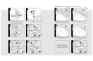
Check Framing
NOTE: Because of the weight of the hood make sure
that the mounting screws are driven into the framing
and not just the drywall. It may be necessary to drill
additional holes in the canopy for proper alignment.