


17
1
(
A)
(
A)
2
(
A
)
(A)
+
1
/
2
”
+1/2”
(
1
.
3
c
m
)
(1.3 cm)
(
A
)
+
1
/
2
”
(
1
.
3
c
m
)
3
-
5
/
8
”
3-5/8”
(
9
.
2
c
m
)
(9.2 cm)
3
-
5
/
8
”
(
9
.
2
c
m
)
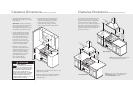
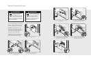
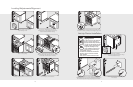
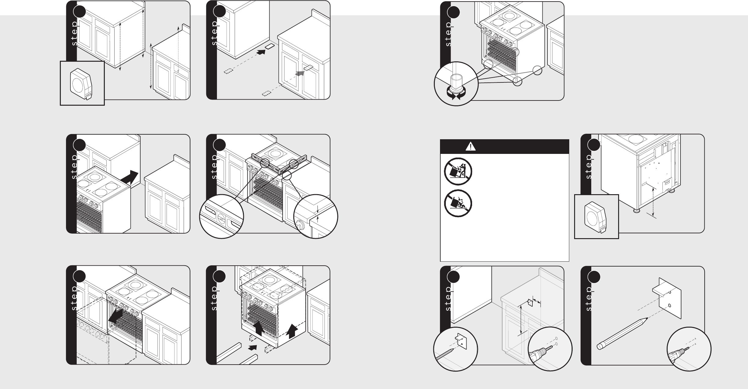
Measure from floor to bottom
of the anit-tip opening located on the back of range.
This will be measurement (A).
Locate anti-tip bracket on rear wall with the top left corner at
measurement (A) plus 1/2” (1.3 cm) from the floor and 3-5/8” (9.2 cm)
from where the right side of range (facing range) is to be located.
3
Mark and drill holes where bracket
will be located.
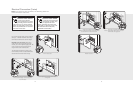
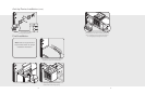
7
Set the high corner of range so that the top of side trim is
3/8” (0.95 cm) above countertop. Level range to high corner.
Anti-tip Device Installation
16
1
2
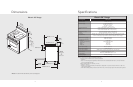
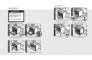
Measure the four corners in cutout area to
verify if flooring is level.
For uneven or sloped floors, level unit with
metal shims only, as the adjustment required may
exceed the thread available in the leg.
3
3
/
8
”
3/8”
(
0
.
9
5
c
m
)
(0.95 cm)
3
/
8
”
(
0
.
9
5
c
m
)
4
Move unit into opening.
Leveling/Adjustments/Alignment
5
Check that unit is level side to
side and front to back. Side trim of the high corner
must be 3/8” (0.95 cm) above countertop.
If leveling is required, move unit out of opening.
6
1
2
1
Lift unit and prop on wood blocks.
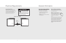
WARNING
Tipping hazard.
To reduce the risk of the appliance
tipping, it must be secured by a
properly installed anti-tip bracket(s).
To make sure the bracket has been
installed properly, look behind the
range with a flashlight to verify
proper installation engaged in the
rear top left corner of the range.
• THIS RANGE CAN TIP.
• INJURIES TO PERSONS CAN RESULT.
• INSTALL ANTI-TIP DEVICE PACKED
WITH RANGE.
• SEE INSTALLATION INSTRUCTIONS.