- 1 -
• The WM25-85SFCD evaporator units shall be installed for ceiling mount
with air supply on both sides and air return on the bottom.
• Supply and return air flow from the evaporator unit shall be unobstructed
for at least 1 foot.
• There is a gravity drain line so that it can not be installed above the
evaporator unit. Otherwise a condensation pump must be used.
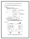
3. Air Sensor
• The air sensor can be located in the wine room or the return air area, but
not the supply air area.
4. Refrigeration Piping and Charging
NOTES: ALWAYS USE THE SUPERHEAT AND SUBCOOLING,
PRESSURE READINGS TO CHARGE REFRIGERANT PROPERLY, THE
LISTED CHARGES ARE FOR REFERENCE ONLY.
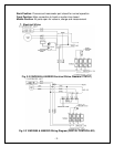
• The installation order starts from condensing unit (including the receiver),
liquid line filter-drier, moisture-liquid indicator (sight glass), liquid line,
evaporator unit (including liquid line solenoid valve and thermostatic
expansion valve or automatic expansion valve), suction line, and returning
to condensing unit.
• The subcooling at the condensing unit shall be around 10°F. The charge
may be complete when there are no more bubbles forming in the sight
glass.
• If equipped with a TXV, the evaporator superheat is set around 8-10 °F for
a 10 °F TD system at factory.
• If equipped with an AXV, the valve is set around 38-40°F at factory and
the superheat at the evaporator unit shall be around 9-18°F under low and
high load at 75°F ambient temperature.
• Low side pressure: 33 psig
• High side pressure: 130 psig at 75 °F ambient temperature and 150 psig
at 90 °F ambient temperature
The line sizes and refrigerant charges are listed as follows.
MODEL
REFRIGERATION
LINES
LIQUID
LINE
SUCTION
LINE
DRAIN
LINE
CHARGE
VINO-
2500SSD
< 50 FT
1/4"
OD
3/8” OD 1/2” OD
R134a/
20 OZ
VINO-
4500SSD
< 50 FT
1/4"
OD
1/2” OD 1/2” OD
R134a/
26 OZ
VINO-
6500SSD
< 50 FT
1/4"
OD
5/8” OD 1/2” OD
R134a/
32 OZ
VINO-
8500SSD
< 50 FT
3/8"
OD
5/8” OD 1/2” OD
R134a/
38 OZ


