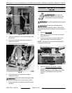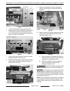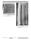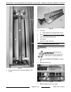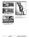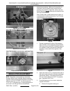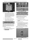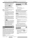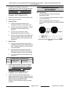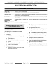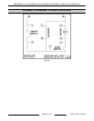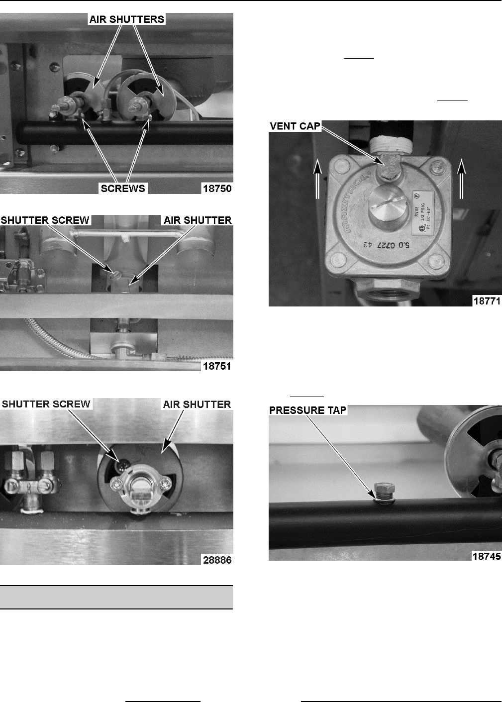
Top Burner Air Shutters
Oven Burner Air Shutter
Charbroiler Burner Air Shutter
REGULATOR ADJUSTMENT
NOTE: Regulators come preset, but should be
checked anytime one is installed. Before adjusting
regulator, check incoming gas line pressure. Incoming
pressure must be 6-14" W.C. for natural gas and
11-14" W.C. for propane gas. If incoming pressure is
not correct, have the gas source checked and
adjusted as necessary. Make sure the regulator is
mounted in the horizontal position with the arrow
pointing in the direction of gas flow. Clean vent cap
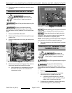
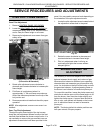
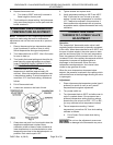
before adjusting. Fig. 66 shows gas flow direction and
vent cap location.
See unit data plate, riveted inside the kick panel, for
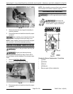
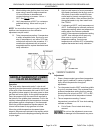
manifold pressure setting information. Fig. 67 shows
manifold pressure tap location.
Fig. 66
1. Connect manometer to either of the pressure
taps provided on the range gas piping between
the burner control valve sets. If pressure taps are
not available, install a pipe tee and hose barb
assembly on the outlet of the regulator. See
TOOLS.
Fig. 67
2. Open the valves to turn on approximately half of
the units burners to the full on position and check
manometer reading. The reading should be 5"
W.C. for natural gas and 10" W.C. for propane
gas. Tolerance is ±0.3" W.C.
3. If manifold pressure is not correct, adjust the
regulator as follows:
A. Remove the regulator closing nut.
ENDURANCE / CHALLENGER MODULAR SERIES GAS RANGES - SERVICE PROCEDURES AND
ADJUSTMENTS
F45471 Rev. A (0615) Page 28 of 38


