


GR SERIES GAS FRYERS - REMOVAL AND REPLACEMENT OF PARTS
F25125 (March 2003) Page 10 of 24
3. Reverse procedure to install and check for
proper operation.
FRY TANK ASSEMBLY
WARNING: DISCONNECT THE
ELECTRICAL POWER TO THE
MACHINE AND FOLLOW LOCKOUT /
TAGOUT PROCEDURES.
WARNING: SHUT OFF THE GAS BEFORE
SERVICING THE UNIT.
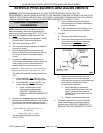
WARNING: ALL GAS JOINTS DISTURBED
DURING SERVICING MUST BE CHECKED FOR
LEAKS. CHECK WITH A SOAP AND WATER
SOLUTION (BUBBLES). DO NOT USE AN OPEN
FLAME.
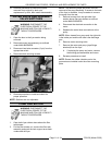
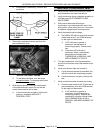
1. Drain shortening from fry tank.
2. Disconnect the gas supply line to allow access
to fryer from all sides.
3. Remove fry baskets, crumb screen and basket
hanger.
NOTE: If the fryer is a battery section, remove
grease strip and split the silicone seal between the
fryer section tanks with a utility knife.
4. Remove front panel as outlined under FRONT
PANEL.
5. On Kleenscreen fryer sections only, remove
bolts securing the drain pipe flange to the
manual drain valve.
6. Remove main burners as outlined under MAIN
BURNERS.
7. Disconnect lead wires and pilot tube from the
gas combination valve.
8. Remove pilot burner as outlined under PILOT
BURNER.
9. Remove control thermostat as outlined under
CONTROL THERMOSTAT.
10. Remove high limit thermostat as outlined under
HIGH LIMIT THERMOSTAT.
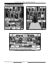
11. Remove gas manifold and hanger assembly
from the fryer.
A. For fryer sections above the filter drawer
assembly on battery fryers or single floor
model fryers (filter ready), remove
mounting nuts securing gas manifold and
hanger assembly to the fryer’s base frame.
B. For other fryer sections in a battery and for
non-filter ready fryers, remove mounting
nuts securing gas manifold and hanger
assembly to the V shaped support bracket.
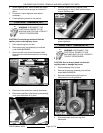
12. On Kleenscreen and filter ready fryers only,
separate the oil return line (hose or flexible
tubing) fitting at the elbow.
13. Separate gas line fitting at the inlet side of the
gas combination valve.
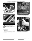
14. Remove bolts securing gas line support bracket
at the left side of gas manifold and hanger
assembly. Allow gas line support bracket to
swing out of way then replace bolts in the
frame. Hand tighten only.
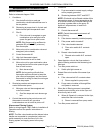
15. Remove screws securing the top of fry tank to
the flue wrap.
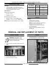
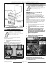
CAUTION: Use care when lifting fry tank
assemblies from the fryer body. Exterior
surfaces of the fryer can be slippery and the
assemblies are heavy.
16. Grasp the fry tank at the top (by flue) and front
lip, then lift fry tank assembly from the fryer
body. Place the assembly on floor or table for
removal of the remaining components.
NOTE: If side access is not available, lift fry tank
assembly from the front of the fryer while rotating
the assembly upwards and toward the front.
17. On Kleenscreen fryers only, remove filter valve
assembly (as necessary) and oil return line
piping from fryer. If removing left side fry tank
above filter drawer assembly, disconnect oil
line and remove discard valve assembly from
fryer.
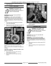
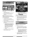
18. Remove bolts securing gas manifold hanger
assembly to the fry tank.
19. Remove screws securing flue box to fry tank
then remove flue box.
20. Remove drain valve.