


GR SERIES GAS FRYERS - REMOVAL AND REPLACEMENT OF PARTS
F25125 (March 2003)
Page 11 of 24
21. Reverse procedure to install all the parts
removed from original fry tank onto
replacement fry tank, then install the assembly.
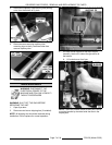
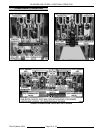
FILTER VALVE AND DISCARD
VALVE SWITCHES
WARNING: DISCONNECT THE
ELECTRICAL POWER TO THE
MACHINE AND FOLLOW LOCKOUT /
TAGOUT PROCEDURES.
1. Open the door to the fryer section being
serviced.
2. Remove burners (as necessary) as outlined
under MAIN BURNERS.
3. Disconnect lead wire connector (2 pin) from the
appropriate switch.
4. Remove switch mounting screws.
5. Reverse procedure to install and check for
proper operation.
NOTE: Switches are not adjustable.
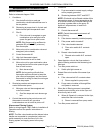
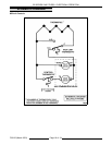
PUMP AND MOTOR
WARNING: DISCONNECT THE
ELECTRICAL POWER TO THE
MACHINE AND FOLLOW LOCKOUT /
TAGOUT PROCEDURES.
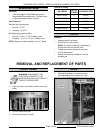
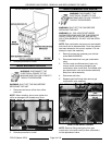
1. Open both fryer cabinet doors above the filter
tank drawer.
2. Pull the filter drawer out, remove the filter tank
assembly and push the tank support arms back
underneath the fryer.
NOTE: The remaining steps are written for front
removal of the pump assembly. If access to the back
of the fryer is available, it may be easier to remove
the pump from the rear.
3. Remove burners from the right side fryer
section above filter tank drawer as outlined
under MAIN BURNERS.
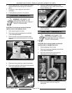
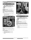
4. Disconnect the electrical connection to the
motor.
5. Separate the swivel hose connections at the
pump.
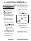
NOTE: When viewed from pump end, the right side
is the intake port and the left side is the discharge
port.
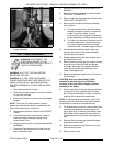
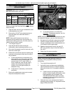
6. Remove motor mounting bolts.
7. Remove the motor and pump (pipe fittings
attached) from the fryer.
A. If replacing the pump and motor, remove
the existing pipe assemblies and reuse.
8. Reverse procedure to install.
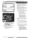
NOTE: Ensure the rubber vibration pad or the
grommets are installed under the motor mounting
plate.