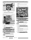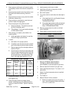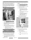
2. Open pressure relief valve until reservoir jacket
is completely vented. Allow valve to snap shut to
seal.
3. Remove pressure relief valve from kettle to vent
the jacket and facilitate draining. Retain for
reuse.
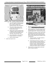
4. Remove draw-off valve or plug valve from kettle
(stationary models only).
5. Place container under kettle to catch fluid and
position it below the sight glass.
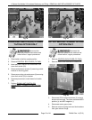
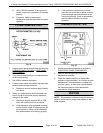
6. Remove sight glass using 36mm socket.
A. Stationary Models - Tilt kettle forward and
lay flat to completely drain.
B. Tilting Models - Turn crank handle clockwise
to tilt the kettle forward.
7. After draining is complete, place kettle in full
upright position.
A. Install sight glass and tighten it to seal the
internal O-ring to prevent leaks.
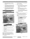
8. To Refill.
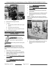
A. With kettle in full upright position.
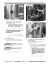
B. If installed, open the manual valve on the fill
port for the reservoir jacket at back of kettle.
C. Remove pipe plug from valve/pipe elbow to
open the fill port.
D. Insert funnel into the fill port and slowly add
mixture of water and heat transfer fluid to the
reservoir jacket. Fill the jacket according to
the volumes listed in the table below. The
level in the sight glass should be 1/3 full.
RESERVOIR JACKET VOLUME
Model
Total Fluid
Volume
(GAL)
Water
(GAL)
Heat
Transfer
Fluid (GAL)
K20GL,
K20GLT
6.5 4.5 2.00
K40GL,
K40GLT
5.75 3.75 2.00
K60GL,
K60GLT
8.75 6.00 2.75
9. Close manual valve (if installed) to prevent leaks.
Hand tighten only.
10. Clean pipe plug threads and apply thread
sealant. Install pipe plug into valve/pipe elbow
opening to close the fill port. Tighten to prevent
leaks.
11. Install pressure relief valve to kettle.
12. Install draw-off valve or plug valve to kettle
(stationary models only).
13. Re-connect power.
14. Turn power switch on and verify low water light is
not lit.
A. If low water light is lit, see Possible Causes
for Low Water Light Lit in
TROUBLESHOOTING.
B. If low water light problem is still not resolved
see Possible Causes for Kettle Does Not
Heat in TROUBLESHOOTING.
15. Remove air from reservoir jacket as outlined
under VENTING.
16. Check kettle for proper operation and leaks
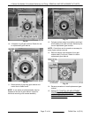
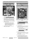
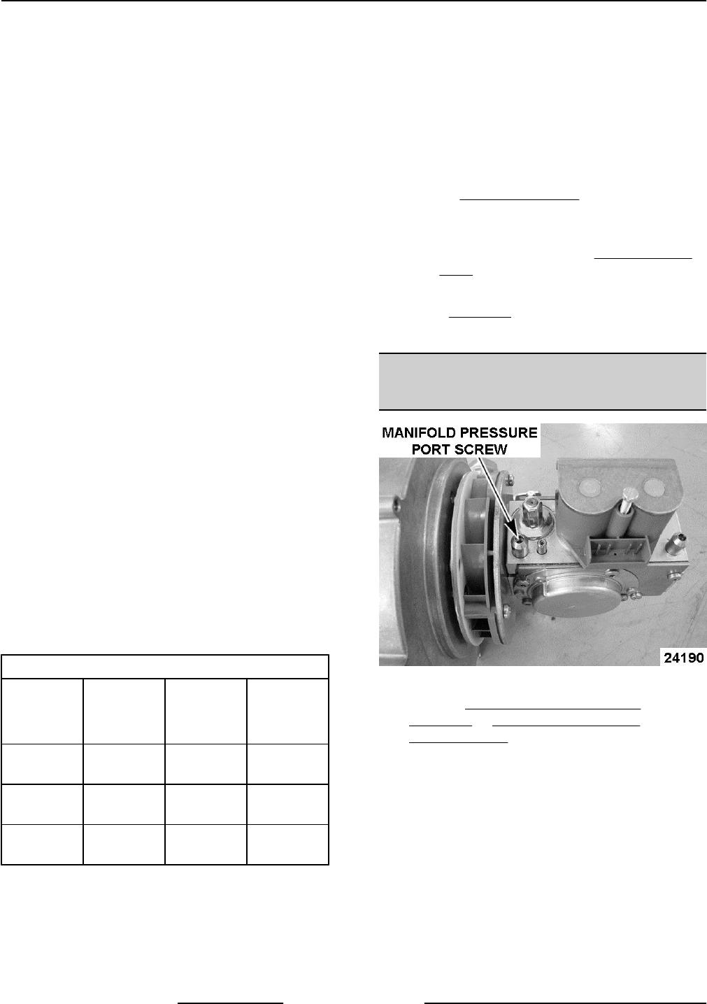
BLOWER INLET PRESSURE
CHECK
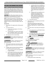
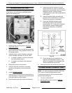
Fig. 39
1. Remove CORNER & REAR PANELS
(TILTING) or SIDE & REAR PANELS
(STATIONARY) to access blower & gas valve.
2. Remove electrical connector from gas valve.
3. Open manifold pressure port. Turn screw 1 to 2
turns CCW.
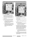
4. Attach U inclined manometer hose to manifold
pressure port.
5. Turn Kettle on.
6. Measure blower vacuum pressure.
A. Blower low speed (during trial for ignition, 7
sec) - Vacuum pressure reading should be
0.27" W.C. to 0.30" W.C.
K Series Gas Kettles 2/3 Jacketed Stationary and Tilting - SERVICE PROCEDURES AND ADJUSTMENTS
F45461 Rev. A (0713) Page 22 of 44


