


-
11 -
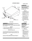
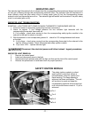
INDICATOR LIGHT
The indicator light illuminates fully to indicate that the corresponding thermostat and burner have turned
on and gas is flowing through the corresponding solenoid valve. The indicator light will illuminate at a
lower intensity when the pilot safety circuit is being made (pilot lit) but the corresponding burner
solenoid valve and thermostat are not on. The indicator light will exhibit no illumination if the pilot safety
circuit is not made (pilot not lit).
INDICATOR LIGHT TROUBLESHOOTING
SYMPTOM – LIGHT DOES NOT COME ON WHEN THERMOSTAT AND BURNER ARE ON.
1. Check for loose or excessively greasy/dirty terminal connections
2. Check for approx. ½ line voltage between the two indicator light terminals with the
corresponding burner and thermostat off.
A. If no voltage – check wires coming in from the corresponding safety ignition module to the
solenoid to the light for shorts or breaks.
3. With thermostat on and corresponding burner lit – check for 120 voltage between both wires
at the light.
A. If no voltage – check wires coming from the corresponding thermostat to the solenoid to the
light for shorts or breaks. Check thermostat and safety ignition module
B. If you have 120V – replace indicator light.
Disconnect the electrical power and follow lockout / tagout procedures
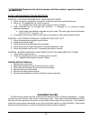
INDICATOR LIGHT REMOVAL
1. Remove the control panel
2. Label and disconnect wires to the light
3. Squeeze the light retainers and slide the light out through the front of the control panel
4. Reverse the procedures to install and check for proper operation
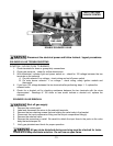
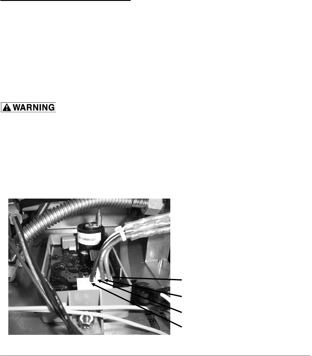
SAFETY IGNITION MODULE
The safety ignition module is a direct
spark ignition control that utilizes a
microprocessor circuit for ignition and
flame sensing. The flame sensing is
achieved via flame rectification. The unit
will continue to spark and keep the
corresponding solenoid valves locked out
until a minimum flame current of 1.0 μA is
achieved.
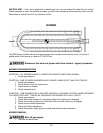
Pin 1
Pin 2
Pin 3
Pin 4