


-
18 -
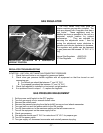
12. Turn power switch and gas supply back on.
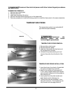
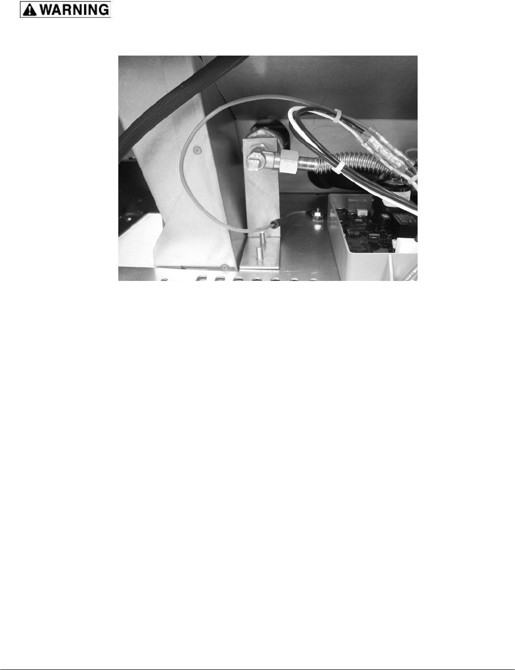
All gas joints disturbed during servicing must be checked for leaks.
Check with a soap and water solution. Do not use an open flame.
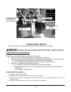
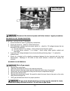
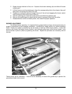
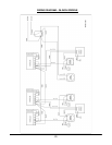
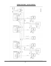
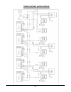
PRESSURE TAP AT #1 BURNER
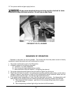
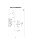
SEQUENCE OF OPERATION
Operation is the same for all size griddles. The neutral wire from the power source is directly
connected to each thermostat and each safety ignition module.
1. The power on/off switch is set to the ON position.
2. Voltage is applied to the following terminals
A. Terminal L1 on each thermostat.
B. Pin 4 terminal of each safety ignition module.
C. Both terminals of the pilot solenoid – energizing the solenoid.
3. The igniter electrode sparks against the pilot head and lights the pilot burner
4. When the pilot flame is sensed – the igniter stops sparking and the igniter safety module allows
voltage to pass to one terminal of each of the corresponding burner solenoid valves and one
terminal of each indicator light – the indicator light illuminates at dim.
5. If the griddle plate temperature is lower than the thermostat set points - the thermostat(s) will
send voltage to the remaining burner solenoid terminal and remaining indicator light terminal.
A. The solenoid will then energize - gas flows to the corresponding burner and is ignited
by the pilot flame.
B. The corresponding indicator light will go from dim to full illumination.