


– 8 –
TESTING THE GAS SUPPLY SYSTEM
When the gas supply pressure exceeds
1
/
2
psig (
3.45 kPa
), the steamer and its individual shutoff valve
must
be disconnected from the gas supply piping system.
When the gas supply pressure is
1
/2 psig (3.45 kPa) or less, the steamer should be isolated from the gas
supply system by closing its individual manual shutoff valve.
FLUE GAS EXHAUST
DO NOT obstruct the flow of flue gases from the flue located on the rear of the steamer.
It is recommended that the flue gases be vented to the outside of the building through a ventilation
system installed by qualified personnel.
Information on the construction and installation of ventilating hoods may be obtained from Vapor
Removal from Cooking Equipment, NFPA-96 (latest edition) available from the National Fire Protection
Association, Batterymarch Park, Quincy, MA 02269.
ELECTRICAL CONNECTION — GAS STEAMERS & STEAM GENERATORS
WARNING: APPLIANCES EQUIPPED WITH A FLEXIBLE ELECTRIC SUPPLY CORD ARE
PROVIDED WITH A THREE-PRONG GROUNDING PLUG WHICH MUST BE CONNECTED INTO
A PROPERLY GROUNDED THREE PRONG RECEPTACLE. IF THE RECEPTACLE IS NOT THE
PROPER GROUNDING TYPE, CONTACT AN ELECTRICIAN. DO NOT REMOVE THE
GROUNDING PRONG FROM THE PLUG.
WARNING: ELECTRICAL AND GROUNDING CONNECTIONS MUST COMPLY WITH THE
APPLICABLE PORTIONS OF THE NATIONAL ELECTRICAL CODE AND/OR OTHER LOCAL
ELECTRICAL CODES.
WARNING:
DISCONNECT THE ELECTRICAL POWER TO THE MACHINE AND FOLLOW
LOCKOUT /
TAGOUT PROCEDURES.
The cord and plug supplied, is a suitable durable cord with molded plug and is provided with a proper
strain relief.
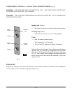
If a hard-wired conduit type connection is desired, remove the cord and plug and connect the electrical
supply circuit to the terminal block located in the boiler control box. A
7
/
8
" (
2.2 cm
)
diameter hole for
1
/2"
(
1.27 cm) trade-size conduit is provided on the side of the control box. Use copper wire suitable for at
least 75°C. A grounding wire must be connected to the ground lug.
The wiring diagram is located on the door of the boiler.
Connect the steamer to the electrical supply after the gas connections have been made.
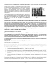
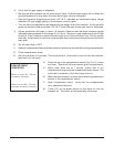
ELECTRICAL DATA
Minimum Circuit Ampacity
Volts Hertz Phase Machine Amps Maximum Protective Device
AMPS
120 60 1 3.0 15
Compiled in accordance with the National Electrical Code, NFPA-70 (latest edition).