


– 7 –
GAS CONNECTION
CAUTION: All gas supply connections and any pipe joint compound used must be resistant to
the action of liquefied petroleum gases.
Codes require that a gas shutoff valve be installed in the gas line ahead of the steamer.
Connect the gas supply line to the gas valve on the steamer. Make sure the pipes are clean and free
of obstructions, dirt and piping compound.
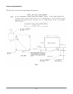
The gas line must be capable of delivering gas to the steamer without excessive pressure drop at the
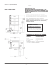
rate specified on the nameplate. Recommended gas line pressure is 7" W.C. (
17.8 cm W.C.) for natural
gas and 11" W.C. (
27.9 cm W.C.) for propane gas. Refer to Fig. 3 on page 8. With adequate gas pressure,
a
3
/4" (1.9 cm) inside diameter black iron pipe to the steamer should be satisfactory. If adequate pressure
is not available, a larger line such as 1" (
2.5 cm) inside diameter may be used to assure adequate gas
delivery.
IMPORTANT: Check burner manifold pressure with a manometer at the
1
/8" (0.32 cm) tap on the gas
valve to make sure it is 4" W.C. for natural gas or 9" W.C. for propane.
WARNING: PRIOR TO LIGHTING, CHECK ALL JOINTS IN THE GAS SUPPLY LINE FOR LEAKS.
USE SOAP AND WATER SOLUTION. DO NOT USE AN OPEN FLAME.
TESTING THE GAS SUPPLY SYSTEM
When test pressures exceed
1
/2 psig (3.45 kPa), the steamer and its individual shutoff valve must be
disconnected from the gas supply piping system.
When test pressures are
1
/2 psig (3.45 kPa) or less, the steamer must be isolated from the gas supply
system by closing its individual manual shutoff valve.
FLUE-GAS EXHAUST — A VENTILATING HOOD IS RECOMMENDED
DO NOT obstruct the flow of flue gases from the flue located on the rear of the steamer. It is
recommended that the flue gases be ventilated to the outside of the building through a ventilation
system installed by qualified personnel.
Information on the construction and installation of ventilating hoods may be obtained from the standard
for the
Removal of Vapors from Commercial Cooking Equipment
, NFPA No. 96 (latest edition),
available from the National Fire Protection Association, Batterymarch Park, Quincy, MA 02269.
ELECTRICAL CONNECTION
WARNING: ELECTRICAL AND GROUNDING CONNECTIONS MUST COMPLY WITH THE
APPLICABLE PORTIONS OF THE NATIONAL ELECTRICAL CODE AND/OR OTHER LOCAL
ELECTRICAL CODES.
WARNING: DISCONNECT THE ELECTRICAL POWER TO THE MACHINE AND FOLLOW LOCKOUT
/ TAGOUT PROCEDURES.
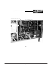
The electrical diagram for the compartments is located on the inside of the upper left side panel. The
electrical diagram for the steam generator is located on the inside of the left front door.
The electrical supply (120 volt, 60 Hertz, 1 Phase) must be connected to the pigtail leads in the junction
box located next to the boiler control box. Use #18 AWG copper wire suitable for at least 105°C
temperature. Connect a grounding wire to the ground lug in the junction box.