


2
Before installing and /or using the cooker hood,
please read these instructions carefully.
Before installing the cooker hood make sure the volt-
age (V), frequency (Hz) indicated on the serial num-
ber plate and specifications on the rating plate on the
inside of the cooker hood correspond to the voltage
and frequency of the mains supply.
The cooker hood must not be installed and connect-
ed to flues where other appliances are installed and
which run off other energy supplies other than elec-
tricity (water heaters - boilers - cookers, range/gas
etc). The extraction hood requires a 125mm extrac-
tion pipe connected directly to the outside with an
opening of a minimum cross section of 150cm
2
.
The hood must be installed with a distance of 650-
750mm between the cooker top/hob and the extrac-
tion hood. The cooker hood must not be installed
above cookers with eye-level grills.
This cooker hood is designed for permanent fixture.
Connect to mains supply. Check voltage and fre-
quency given on the rating plate located on the
inside of the hood. Connect the mains cable to a
power socket or to a double pole switch with a con-
tact gap of at least 3mm. The mains cable (type
H05VV- F 2x 0.75 mm
2
) is connected to terminals
marked with the letters L (power line) and N (neutral)
mounted on the hood and is secured in position by a
cable gland. The mains cable must be connected to
a suitable and easily accessible fixed power point.
As the electrical installation must comply with the
laws and regulations in force only a qualified and
authorised electrician must install the hood including
connecting it to a double pole switch with a contact
gap of at least 3mm.
Connect the mains cable if provided with a plug to a
power socket. The user must have access to the
power socket to be able to connect and disconnect
the plug once the hood is mounted and fixed or the
mains cable can be plugged into a socket with a dou-
ble pole switch with a contact gap of at least 3mm.
The manufacturer will not be responsible if the gov-
erning health and safety laws are not observed
which permit safe and correct use of the hood and
electrical connections.
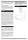
The hood is intended for fitting on the wall. Position
the hood 70cm above the hob. Remove the metal
anti-grease filters. Position the hood against the wall
and mark on the wall the position of the support
holes. Using a drill bit with a diameter of 6mm.,
make holes in the wall on the reference marks made
previously. Insert the expansion fixings in the holes
and then screw the support screws half-way in.
Hook the hood onto the screws and fasten it onto the
wall, tightening all the screws. Fit the coupling to the
top of the hood using self tapping screws provided.
Connect the discharge pipe to the coupling. Replace
the metal anti-grease filters.
The steel ducting for the hood is to be fixed to the
wall using the bracket supplied, the bracket is to be
fixed nearest the ceiling and fixed to the end of the
duct with slots in it.
The control panel is situated on the front of the hood
and comprises of 5 push button switches with the fol-
lowing functions:
Fan ON/OFF switch
Low fan speed
Medium fan speed
High fan speed
Light ON/OFF switch
Before servicing or repairing the hood make sure the
appliance is disconnected from the mains supply
either by removing the plug or switching the power
socket to OFF.
a) Cleaning
“NOTE: the areas behind the filters are not
intended to be cleaned”
Clean the external parts with non-corrosive liquid
detergents, avoiding the use of abrasive powders or
of brushes.
b) Cleaning the metal anti-grease filter
The saturation of greasy residue in the metal filter
may cause increased inflammability. In order to pre-
vent possible fires, the metal filter must be washed
GENERAL GUIDELINES INSTRUCTIONS FOR ASSEMBLY
CONTROL PANEL
MAINTENANCE
INSTALLATION
ELECTRICAL CONNECTION