


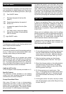

The control panel is situated on the front of the hood
and comprises of a digital display and 5 touch con-
trol switches with the following functions: (See Fig.9)
Fan ON/OFF Switch
Reduces the speed of the fan (Min
speed 1)
Digital display,displays the speed of
the fan 1-6
Increases the speed of the fan (Max
speed 6)
OFF delay switch, press once display
flashes, fan switches off automatically
after 15 minutes
Light ON/OFF switch
The electronic controls on your ducting cooker hood
have multiple functions-features:
Motor on-off Function
The motor is turned on and off by pressing push-but-
ton no.1. When you turn on the cooker hood it auto-
matically starts running at the third speed.
Timer Function
This function permits you to program your cooker
hood so that the motor and lights turn off automati-
cally 15 minutes after you have activated this func-
tion. To program press push-button no.4. At the bot-
tom on the right of the display a point will flash indi-
cating that the timer function is activated.
Lights on-off Function
To turn the lights on and off press push-button no. 5.
Specific Features
The electronic controls provided on your ducting
cooker hood have advanced features to facilitate
maintenance and correct utilisation.
Prompt-Clean Metal Filters
After every 30 hours of use a microprocessor,
prompts the user that it is time to clean the metal
grease filters to guarantee better ducting perform-
ance and to improve hygiene. This prompt is indicat-
ed by the letter “A” which flashes on the display.
To delete this prompt, once the filters have been
cleaned and with the cooker hood off (not powered),
maintain push-button 2 pressed for more than 5 sec-
onds. When you press this push-button the letter “A”
will come up on the display and then disappear after
5 seconds. The microprocessor zeros the number of
hours and starts a new count from zero until reach-
ing 30 hours prompting this maintenance procedure.
If there is an appliance fitted in the vicinity which
requires air for combustion, additional air vents will
be required to alleviate the possibility of spillage of
products of combustion, from the appliance/flue
while the fan is in operation. Refer to B.S. 5440 Part
2 & I.S. 813.
Where such an installation exists a test for spillage
should be carried out with all appliances requiring air
for combustion and all extraction fans running at
maximum rate, (i.e. tumble dryers, extraction fans)
with all external windows and doors closed.
If spillage occurs following the above operation, an
additional air vent of sufficient size to prevent this
occurrence should be installed.
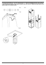
1. Fix the ceiling bracket to the ceiling, making sure
that the riveted brackets for fixing the stainless
steel casing are to the side. Adjust the chimney
section to the required length. See Fig. 2 & 2a.
2. Slide the stainless casing over the chimney
section keeping vents to the side. See Fig.3.
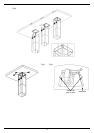
3. Mount the chimney section on the ceiling bracket,
note tabs must fit into the slots on the ceiling
bracket to hold this section in place while fitting
the fixing screws. See Fig.4.
4. Fit 4 fixing screws one in each corner. See
Fig. 5. Fit the glass onto the hood section using
clamps provided (See Fig 6). Connect the plug
and socket between the chimney and the hood
section.
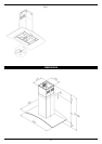
5. Lift the glass section into place, the clip on either
side will hold hood in place while fitting the fixing
screws. See Fig 7.
CONTROL PANEL
VENTILATION
FITTING INSTRUCTIONS
SPECIFICATIONS
3