


A-8
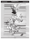
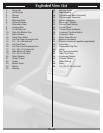
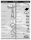
Exploded View List
1. Hinge Pin
2. Left Endcap
3. Shroud
4. Handle
5. Warming Rack
6. Cooking Grates
7. Flavorizer
®
Bars
8. Cooking Box
9. 1/4-20 keps nut
10. Slide Out Bottom Tray
11. Work Surface
12. Catch Pan Holder
13. Left Trim Rear Assembly Arm
14. 1/4 - 14 x 5/8 inch bolt
15. Left Trim Piece
16. Left Trim Front Assembly Arm
17. 1/4 - 20 x 2-1/4 inch bolt
18. Side Swing-Up Table
19. 1/4 - 20 x 1 inch bolt
20. Nylon Washer
21. Caster Frame
22. Caster
23. Bottom Rack
24. Wheel
25. Hubcap
26. Hair Pin Cotter
27. Right Endcap
28. Thermometer Bezel Assembly
29. Thermometer Assembly
30. Handle Hardware
31. Warm-Up™ Basket
32. Control Panel Knobs
33. Control Panel
34. Control Panel Hardware
35. Crossover
®
Ignition Button
36. Crossover
®
tube
37. Front / Rear Burner
38. Manifold Hardware
39. Manifold, Hose and regulator (assembled)
40. Catch Pan
41. Disposable Drip Pan
42. Igniter
43. Top Frame Assembly
44. Right Trim Piece
45. Condiment Basket
46. Cylinder Glides
47. Wheel Frame
48. Hose
49. 1/4 - 20 x 1 3/4 inch bolt