


5
INSTALLATION (continued)
WARNING: ELECTRIC SHOCK HAZARD
All servicing requiring access to non-insulated electrical components must be
performed by a factory authorized technician.
DO NOT open any access panel which requires the use of tools. Failure to follow this
warning can result in severe electrical shock.
CAUTION:
RISK OF
DAMAGE
DO NOT connect or energize
this appliance until all
installation instructions are
read and followed. Damage
to the appliance will result if
these instructions are not
followed.
CAUTION:
ELECTRIC
SHOCK HAZARD
The ground lug of fryers must
be connected to a suitable
building electric ground.
IMPORTANT:
Damage due to being
connected to the wrong
voltage or phase is NOT
covered by warranty.
IMPORTANT: Refer to the General Layout Data packed with the fryer
for wire size requirements and other installation data.
F-55 STS FRYER ELECTRICAL INSTALLATION
F-55 fryers must be connected directly to an appropriately sized electric
circuit. Conduit and strain relief must be provided by the electrician.
F-55 fryers require a 208VAC or 240VAC 20 amp three-phase circuit
with ground.
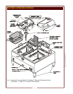
Raise the element head, remove the frypot and the cover at the inside
rear of the fryer to gain access to the terminal block. The electrical inlet
is provided by a knock-out in the rear panel.
If an equipment shutdown interface is required by local fire code, the
flame sensor terminal block may be accessed by removing the cover at
the inside rear of the fryer Replace the jumper of the terminal block
with wiring to a normally closed contact of the building fire management
system.
DO NOT connect power to the flame sensor terminal block. Wiring and
contacts must be capable of handling 20 amps.
F-85 FRYER ELECTRICAL INSTALLATION
F-85 fryers must be connected directly to an appropriately sized electric
circuit. Conduit and strain relief must be provided by the electrician.
F-85 fryers require either a 240VAC 50 amp single phase circuit with
ground; a 208VAC or 240VAC 40 amp three phase circuit with ground,
or a 480VAC 20 amp three phase circuit with ground. Units are shipped
from the factory wired for three phase. Conversion of 240VAC units to
single phase must be performed in the field by the electrician.
Raise the element head, remove the frypot and the cover at the inside
rear of the fryer to gain access to the terminal block. The electrical inlet
is provided by a knock-out in the rear panel.
F-101 and F-1725 FRYER ELECTRICAL INSTALLATION
F-101 and F-1725 fryers must be connected directly to an appropriately
sized electric circuit. Conduit and strain relief must be provided by the
electrician. F-101 fryers require a 208VAC or 240VAC 40 amp three
phase circuit with ground,
F-1725 fryers require a 208VAC or 240VAC 50 amp three phase circuit
with ground, Units are shipped from the factory wired for three phase.
F-101 and F-1725 fryers are not approved for conversion to single
phase.
Raise the element head, remove the frypot and the cover at the inside
rear of the fryer to gain access to the terminal block. The electrical inlet
is provided by a knock-out in the rear panel.
302 p/n 304356 OpM CT Fryers STS