9
INSTALLATION
NOTE: DO NOT discard
the carton or other packing
materials until you have
inspected the appliance for
hidden damage and tested it
for proper operation.
Refer to SHIPPING DAMAGE
CLAIM PROCEDURE on the
inside front cover of this
manual.
WARNING:
Risk of
personal injury
Installation procedures must
be performed by a qualified
technician with full knowledge
of all applicable electrical
codes. Failure can result in
personal injury and property
damage.
WARNING:
Fire Hazard
Avoid storing flammable or
combustible materials near
the appliance.
UNPACKING & INSPECTION
Carefully remove the appliance from the carton. Remove all
protective plastic film, packing materials and accessories from the
Appliance before connecting electrical power or otherwise performing
any installation procedure.
Carefully read all instructions in this manual and the Installation
Instruction Sheet packed with the appliance before starting any
installation.
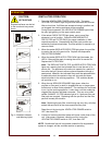
Read and understand all labels and diagrams attached to the
appliance.
Carefully account for all components and accessories before
discarding packing materials. Store these components in or near the
appliance for later use. These items must be installed before operating
the appliance.
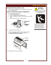
1 ea. FIRE SUPPRESSION AGENT (ANSULEX® Low pH, 1.5 GAL.)
See Material Safety Data Sheet, page 28.
1 ea. FIRE SUPPRESSION MEDIA TANK
1 ea. FIRE SUPPRESSION TANK CHARGING CARTRIDGE
1 ea. GREASE BAFFLE
1 ea. FILTER PACK ASSEMBLY
1 ea. PRE-FILTER HOLDER with PRE-FILTER
1 ea. GREASE DRIP TRAY
1 ea. GREASE DRAWER ASSY FOR GRIDDLE
2 ea. 6” SIDE SPACERS
1 ea. LITERATURE PACKAGE
Additionally:
2 ea. HOTPLATE DRIP PANS (spiral elements only)
2 ea. ELEMENT SUPPORTS (spiral elements only)
2 ea. DRAWER PANS (if unit has optional drawer warmers)
SETUP
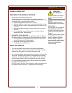
Setup the appliance only on a firm level surface. Non-combustible
material is recommended.
Refer to the Installation Instruction Sheet for required clearances.
Maintain required clearances between the appliance and adjacent
combustible surfaces. Verify 6” left and right side clearances to
combustible construction. This appliance requires a minimum of 8 ft
(96”) (floor to overhead) to allow for adequate exhaust.
IMPORTANT: Provided 6" side spacers (item 58) must be installed on
the appliance.
Factory installed side shields (item 57) are required.
Verify that the VENTILATOR HOOD ASSEMBLY is properly and
securely assembled to the cooking appliance before beginning the
installation procedure.
If a remote manual pull station is to be installed, replace the rear
casters with legs.
Level the unit after it is in its final position. Using a spirit level, verify
that the unit is level front-to-back and side-to-side.


