


1. If local codes permit connection of the frame ground-
ing conductor to the neutral (white wire), connect the
green and white wire from the supply cable of the
appliance together and to the neutral (white) wire in
the junction box. Connect the remaining wires from
the supply cable, matching the colors, to the wires in
the junction box.
2. If local codes DO NOT permit frame grounding to the
neutral, separate the white and green wires that
extend out of the end of the supply cable of the
appliance. Connect the white wire from the supply
cable to the neutral wire in the junction box.
Connect the black and red wire from the supply cable,
matching the colors, to the corresponding wires in the
junction box. The green wire MUST now be used to
ground the appliance in accordance with local electri-
cal codes. Connect the green ground wire to a
grounded cold water pipe*or to the grounded lead in
the service panel. Do not ground to a gas supply pipe.
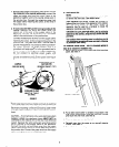
Do not connect to electrical power supply until
appliance is permanently grounded. Connect the
ground wire before turning on the power. See Figure
2.
COPPER
GROUND WIRE
GROUNDED COLD
WATER PIPE
(REMOVE PAINT, ETC.)
GROUND CLAMP’
NUTS FIRMLY
(MUyNBp;p;yHT
FIGURE 2
*Cold water pipe must have metal continuity to electrical
ground and not be interrupted by plastic, rubber or other
electrically insulating connectors (including water meter
or pump) without adding a jumper wire at these connec-
tions.
CAUTION - If connecting to a four-wire electrical system
(MOBILE HOME) the appliance frame MUST NOT be
connected to the neutral wire of the four-wire electrical
system. Separate the white and green wires that extend
out of the end of the supply cable of the appliance.
Connect the white, red and black wires from the supply
cable, matching the colors, to the corresponding wires in
the junction box. Connect the green wire from the supply
cable to the ground wire in the junction box.
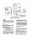
3. INSTALLATION
NOTE:
Before installing the oven in the cutout, it may be helpful
to remove the oven door. See details below.
Insert appliance into cut-out. Screws are provided for
fastening the front frame of the appliance to the cabinet.
The mounting holes in the front frame of
appliance may be used as a template to locate the
appliance mounting screw holes.
CAUTION: For your personal safety, and to minimize
potential personal injury, this oven must be securely
fastened to the cabinet, using the four screws that are
provided.
Use caution when mounting oven in cutout so you do
not overtighten screws and cause porcelain chippage
or puncture oven cavity.
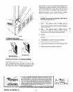
TO REMOVE OVEN DOOR-SELF-CLEANING MODELS
(Door to be removed for installation only).
1. Remove the two screws, one on each side of the inner door
panel. See View A.
SCREW
(1
VIEW A
\ ’
2. Put an allen wrench (5132” or smaller) or equivalent in the
hole in each of the hinges. Close the oven door until the
pins touch the oven front. See View 8.
3. The oven door can now be lifted off.
4. Reinstall oven door the same as on non-self cleaning
models. (See page 4)
5. Reinstall the door mounting screws.
3