


Water
requirements
The cold water line to the ice maker
requires l/4.-0 D. soft copper
tubing.
A threaded compression fitting to
connect the water line to the inlet
valve is I” the parts bag
Install a shut-off valve in the water
lhe where It can be easy to access
Drain
requirements
This appliance is equipped with a
gravity drain and a 4’.long.
5/a’- 0.D rubber, drain tube
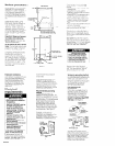
Recommended method
Install a l-114’ minimum diameter
standplpe directly below the drain
tube outlet. (See Panel A for
dimensions )
It may be desirable to Insulate the
drain line up to the drain inlet to
minimize condensation on the drain
tube
Alternate method
Ii a drain connection directly below
the drain tube outlet Is not available.
a drain pump (Part No EKDPB) WIII
need to be installed. The drain
pump, available from your local
authorized parts distributor. lifts water
to an avaIlable drain.
Electrical Shock Hazard
Disconnect power supply.
Failure to do so could result in
electrical shock or personal
injury.
1. Follow steps 1 through 10 of the
Snow start .” section
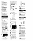
2. Install the drain oumo on the floor
near the center of the rear
wall of the cabinet opening. The
side of drain pump with the
discharge tube should face the rear
of the obenlng
3 Remove the rubber drain hose
and connect the bin drain directly to
the pump using 5/B” I D. plastic hose.
(See Figure 4.)
4 Run pump drain hose to drain
(See Figure 4.)
5 Run the power supply cord from
the puma throuah the hole I” the
rear’of the ice Gaker. (See Figure 4.)
Y
Figure 4
6 Remove the two screws attaching
the afr grille to the ice maker.
Remove the air grille (See Figure 5 )
Figure 5
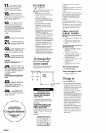
7 Remove and save the shunt from
the ice maker receptacle Plug the
drain pump, power supply cord into
the receptacle. (See Figure 6.)
Panel B
NOTE:
Do Not discard shunt. The shunt
must be reattached to the ice
maker when the Ice maker is
operated without a drain pump.
See Installation Instructions
included with drain pump.
Figure 6
7. Reattach the air grille to the Ice
maker with the two screws
Now start...
1
Carefully place carton on Its
H side. Open the bottom flaps
CD
open twnom 1lOPl
2
Set carton upright with all
H four. bottom flaps folded
outward. Remove carton from Ice
maker.
3
Remove all tape and
n packing material from the
outside and InsIde of the ice maker
4.
Remove parts
package from
Inside Ice
maker bin
5
Remove the two screws
W attaching the air grille to the
Ice maker. Remove the air grille.
6
Turn the fan by hand to
n check that It moves freely
7
Slightly loosen,
but Do Not
n remove, the thumb screws
holding the cutter grid and water
pan in place
8
Rough in l/4’-0.D soft
n copper tubing from the cold
water supply line
PosItion tubing so
that It can enter the access hole
located I” the rear of the ice maker
cabinet Place tubing in the center
of the opening and allow enough
tubing so that It extends beyond the
cablnet front when the icemaker is
pushed back Into position [See
Panel A),
9
Install a shutoff valve I” the
n
water line where It can be
easily used
10
Flush the water line into a
n bucket to get rid of any
particles that may clog the Inlet
valve. Turn the shutoff valve to the
“off” posltion.
Failure to do so could result in
11
Determine which type of
n drain method you need
and follow the *Drain requirements”
Instructions for that method on
Panel B.
Move Ice maker close to
Its final position.
Electrical Shock Hazard
Disconnect power supply.
Failure to do so could result in
electrical shock or personal
12
Plug the electrical cord
1 Into the grounded outlet.
13
Insert the cold-water
n suoolv tublna through the
hole in the r&r bf the i:e maker
Slide the ice maker Into place.
Center the Ice maker I” the opening.
Remove the cardboard/hardboard
14
Attach the hose by the
n threaded. compreSSlon
fitting to the ice makers cold-water
inlet valve. Bend the cold-water
supply tubing up toward the flttlng.
Attach the cold-water supply tubing
to the fitting
Check for good fit
15
Check the levelness of the
n ice maker from front to
back and side to side
The ice
maker must be level for proper
operation. Shim the ice maker with
masonlte or any hard, permanent
material so that It is level and held
tightly I” place
If local codes
require. seal Ice maker cabinet to
floor with an approved caulking
compound
16
Check that all parts have
n been installed and that no
steps were skipped. Check that you
have all the tools you started with.