


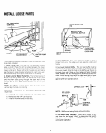
INSTALL LOOSE PARTS
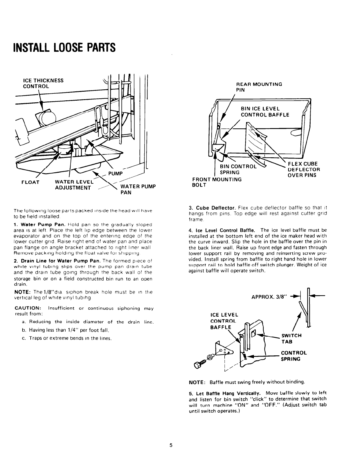
ICE THICKNESS
.
FLOAT
WATER LEVEL
ADJUSTMENT / ’ ;;lER PUMP
\’
The following loose parts packed InsIde Ihe head WIII have
to be field Installed
1. Water Pump Pan. Hold pan so the gradua!ly sloped
area IS at left Place the left 11p edge between the lower
evaporator and on the top of the entering edge of the
lower cutter grid Raise right end of water pan and place
pan flange on angle bracket attached to right liner wall
Remove packing holding the float valve for shlpplng
2. Drain Line for Water Pump Pan. The formed piece of
white vlnyl tubing slips over the pump pan drawn tube
and the drain lube going through the back wall of the
storage bin or on a field constructed bin run to an open
drain.
NOTE: The 1/8”dia siphon break hole must be In IIle
vertical leg of white vinyl tubing
CAUTION: Insufficient or continuous siphoning may
result from:
a. Reducing the inside diameter of the drain line.
b. Having less than l/4” per foot fall,
c. Traps or extreme bends in the lines.
FRON
BOLT
REAR MOUNTING
PIN
T hhl
SPRING
3UNTING
- DEFLECTOR
OVER PINS
3. Cube Deflector. Flex cube deflector baffle so that it
hangs from pins. Top edge will rest against cutter grid
frame
4. Ice Level Control Baffle. The ice level baffle must be
installed at the bottom left end of the ice maker head with
the curve inward. Slip the hole in the baffle over the pin in
the back liner wall. Raise up front edge and fasten through
lower support rail by removing and reinserting screw pro-
vided. Install spring from baffle to right hand hole in lower
support rail to hold baffle off switch plunger. Weight of ice
against baffle will operate switch.
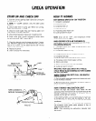
APPROX. 318”
+I”-
SWITCH
TAB
CONTROL
SPRING
NOTE: Baffle must swing freely without binding.
5. Let Baffle Hang Vertically. Move baffle slowly to left
and listen for bin switch “click” to determine that switch
will turn machine “ON” and “OFF.” (Adjust switch tab
until switch operates.)
5