


GENERAL INFORMATION
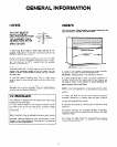
LOCATE
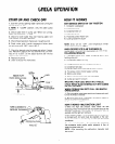
THIS UNIT MUST BE
INSTALLED IN AN
AREA PROTECTED FROM
THE ELEMENTS, SUCH
AS WIND, RAIN, WATER
SPRAY OR DRIP.
110” F
90’ F
1
OPERATING
1 BEST
LIMITS
1
\ RANGE
70’ F
55” F
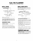
1. Unit must be at least 3” from back wall for air cir-
culation. Adequate air circulation must be provided on top
and other sides for performance.
2. If air cooled ice maker is installed in a closed room, 1000
C.F.M. of air must be exchanged through the room to main-
tain the room air at 10’ F. warmer than the available
ambient air temperature.
3. The head may be installed on either a Whirlpool bin or
field-constructed bin. In either case, be sure the floor will
support the combined weight of the ice maker and the
stored ice cubes. (Approximately 300 Ibs. per leg, if using a
Whirlpool bin.)
4. Level bin before installing head. The ice maker head
must be level to insure proper water flow over the freezing
plates.
If height of ice maker exceeds 90” when installed on a
Whirlpool bin and bin expander a leg kit model CECK3
must be used for additional stability.
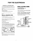
TO INSTALLER
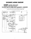
This machine is shipped from the factory with 15.6 Volts
supplied to the cutter grids.
If In your area the water or low voltage conditions cause
Ice slabs to pile up on the cutter grids. a higher voltage
tap on the transformer secondary may be wired to the
cutter grids.
Check the Information label at the transformer.
Water treatment may be advisable because poor quality
water can cause marginal operation or malfunction and
increase cleaning frequency and maintenance costs.
Contact your local Whirlpool Commercial Ice Machine
Dealer for recommendations.
UNPACK
This item is heavy. When handling, use proper equipment and
care to protect it, yourself, stairs and floors.
FRONT PANEL
OH SCREWS -O
r
LOOSE PACKAGING BASE
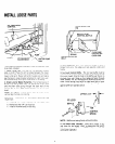
1. Using 2” x 4” blocks or shipping foam corners carefully
lay cabinet on its back to remove packaging base.
CAUTION: Packaging base is not attached to product.
2. Leaving shipping tape in place, use proper equipment to
carefully position the ice maker head on bin. Always lift
the head to move it into position to avoid damaging the
gasket between the bin and head.
NOTE: On a field-supplied bin, a food grade silicone rubber
sealant must be used to insure a tight seal between the head
and bin.
3. Fasten the head to the bin with screws and brackets
provided. (Screws are in cabinet sides and back. Brackets
are in small parts bag.) Use two brackets on back and one
on each end towards front corners.
4. Remove front panel by removing two screws and lifting
panel off.
5. Examine carefully for concealed damage. If damaged,
save the carton and have carrier examine product and make
inspection report.
6. Remove all tape, cardboard, and packaging materials
from inside ice maker head, i.e. expansion valve shipping
pad and water float tape.
2