


1. BEFORE YOU BEGIN 3. CARPENTRY
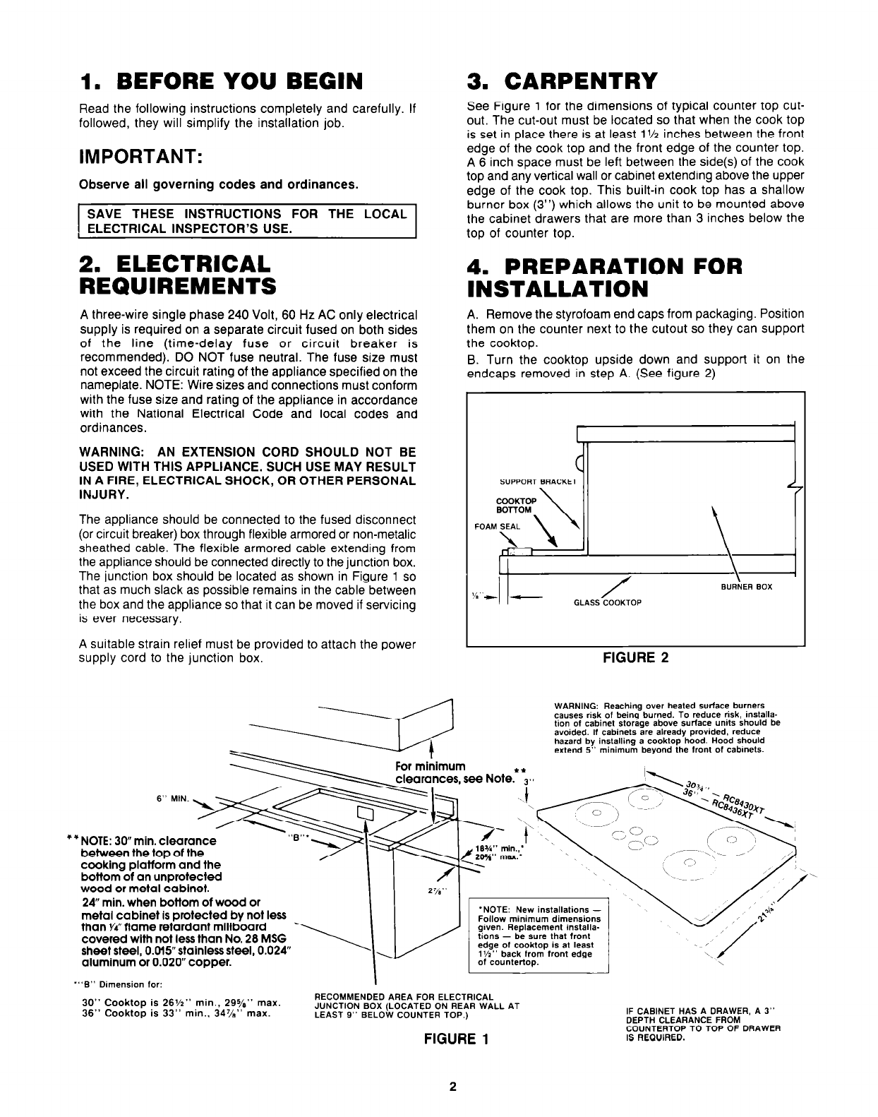
See Figure 1 for the dimensions of typical counter top cut-
out. The cut-out must be located so that when the cook top
is set in place there is at least 1% inches between the front
edge of the cook top and the front edge of the counter top.
A 6 inch space must be left between the side(s) of the cook
top and any vertical wall or cabinet extending above the upper
edge of the cook top. This built-in cook top has a shallow
burner box (3”) which allows the unit to be mounted above
the cabinet drawers that are more than 3 inches below the
top of counter top.
Read the following instructions completely and carefully. If
followed, they will simplify the installation job.
IMPORTANT:
Observe all governing codes and ordinances.
SAVE THESE INSTRUCTIONS FOR THE LOCAL
ELECTRICAL INSPECTOR’S USE.
2. ELECTRICAL
REQUIREMENTS
A three-wire single phase 240 Volt, 60 Hz AC only electrical
supply is required on a separate circuit fused on both sides
of the line (time-delay fuse or circuit breaker is
recommended). DO NOT fuse neutral. The fuse size must
not exceed the circuit rating of the appliance specified on the
nameplate. NOTE: Wire sizes and connections must conform
with the fuse size and rating of the appliance in accordance
with the National Electrical Code and local codes and
ordinances.
WARNING: AN EXTENSION CORD SHOULD NOT BE
USED WITH THIS APPLIANCE. SUCH USE MAY RESULT
IN A FIRE, ELECTRICAL SHOCK, OR OTHER PERSONAL
INJURY.
The appliance should be connected to the fused disconnect
(or circuit breaker) box through flexible armored or non-metalic
sheathed cable. The flexible armored cable extending from
the appliance should be connected directly to the junction box.
The junction box should be located as shown in Figure 1 so
that as much slack as possible remains in the cable between
the box and the appliance so that it can be moved if servicing
is ever necessary.
A suitable strain relief must be provided to attach the power
supply cord to the junction box.
4. PREPARATION FOR
INSTALLATION
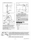
A. Remove the Styrofoam end caps from packaging. Position
them on the counter next to the cutout so they can support
the cooktop.
B. Turn the cooktop upside down and support it on the
endcaps removed in step A. (See figure 2)
FIGURE 2
WARNING: Reaching over healed surface burners
causes risk of being burned. To reduce risk, installa-
tion of cabinet storage above surface units should be
avoided. If cabinets are already provided, reduce
hazard by installing a cooklop hood. Hood should
extend 5” minimum beyond the front of cabmets.
wood or metal cabinet.
24” min. when bottom of wood or
metal cabinet is protected by not less
than YCflame retardant millboard
covered with not less than No. 28 MSG
sheet steel, O.Ol5” stainless steel, 0.024”
aluminum or 0.020” copper.
Follow minimum dimensions
given. Replacement installa-
tions - be sure that front
edge of cooktop is at least
l’/r” back from front edge
“‘B” Dimension for:
30” Cooktop is 26%” min., 295/a” max.
36” Cooktop is 33” min.. 34%” max.
I
RECOMMENDED AREA FOR ELECTRICAL
JUNCTION BOX (LOCATED ON REAR WALL AT
LEAST 9” BELOW COUNTER TOP.)
FIGURE 1
IF CABINET HAS A DRAWER, A 3”
DEPTH CLEARANCE FROM
COUNTERTOPTO TOPOF DRAWER
IS REQUIRED.
2