


8
Use only pipe-joint compound made for use with Natural and
LP gas.
Do not use TEFLON
®
tape. You will need to determine the fittings
required depending on your installation.
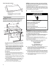
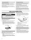
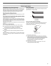
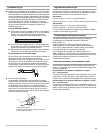
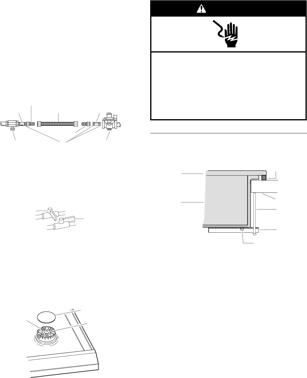
Typical flexible connection
1. Apply pipe-joint compound made for use with LP gas to the
smaller thread ends of the flexible connector adapters (see G
in the following illustration).
2. Attach 1 adapter and nipple to the gas pressure regulator and
the other adapter and nipple to the gas shutoff valve. Tighten
both adapters and nipples.
3. Use a ¹⁵⁄₁₆" combination wrench and pliers to attach the
flexible connector to the adapters. Check that connector is
not kinked.
Complete Connection
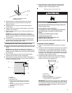
1. Open the manual shutoff valve in the gas supply line. The
valve is open when the handle is parallel to the gas pipe.
2. Test all connections by brushing on an approved
noncorrosive leak-detection solution. Bubbles will show a
leak. Correct any leak found.
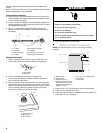
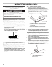
3. Remove surface burner caps and grates from parts package.
Align notches in burner caps with pins in burner base. Burner
caps should be level when properly positioned. If burner caps
are not properly positioned, surface burners will not light.
Place burner grates over burners and caps.
4. Plug into a grounded 3 prong outlet.
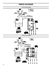
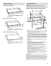
Attach Cooktop to Countertop
NOTE: This section applies only if you are using clamping
brackets.
1. Place the 2½" (6.4 cm) clamping screws into the brackets.
2. Check that the cooktop is still level.
3. Use a flat-blade screwdriver to tighten the screws against the
countertop. Do not overtighten.
A.
³⁄₈
" nipple
B.
³⁄₈
" adapter
C. Flexible connector
D. ½" nipple
E.Gas pressure regulator
F. ½" adapter
G. Use pipe-joint compound.
H. Manual gas shutoff valve
A.Closed valve
B. Open valve
A. Igniter electrode
B. Burner cap
C. Burner base
A
B
C
D
E
G
F
H
A
B
A
B
C
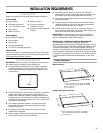
A. Glass cooktop
B. Cooktop base
C. Attachment screw
D. Clamping bracket (extends
far enough beyond cooktop
base to allow installation of
clamping screws)
E. 2½" (6.4 cm) clamping screw
F. Coun ter top
G. Foam seal
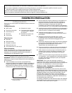
Electrical Shock Hazard
Plug into a grounded 3 prong outlet.
Do not remove ground prong.
Do not use an adapter.
Do not use an extension cord.
Failure to follow these instructions can result in death,
fire, or electrical shock.
WARNING
A
B
C
D
E
F
G