


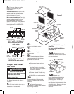
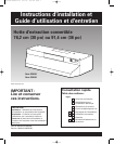
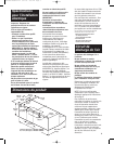
Prepare and install
the hood
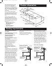
3-1/4" x 10" (8.3 x 25.4 cm)
RECTANGULAR VERTICAL
vent system
5
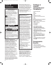
4.
From the diagrams below,
select the diagram for your
installation.
Vented installations: Cut the vent
system and electrical wiring
access holes as required. Either
wiring hole can be used.
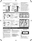
Non-vented installations: Cut only
the one 1-1/4" (3.2 cm) dia. wiring
access hole required. If wiring
through the top, use location
shown in VERTICAL vent systems.
If wiring through the back, use
location shown in HORIZONTAL
vent system.
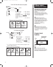
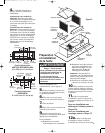
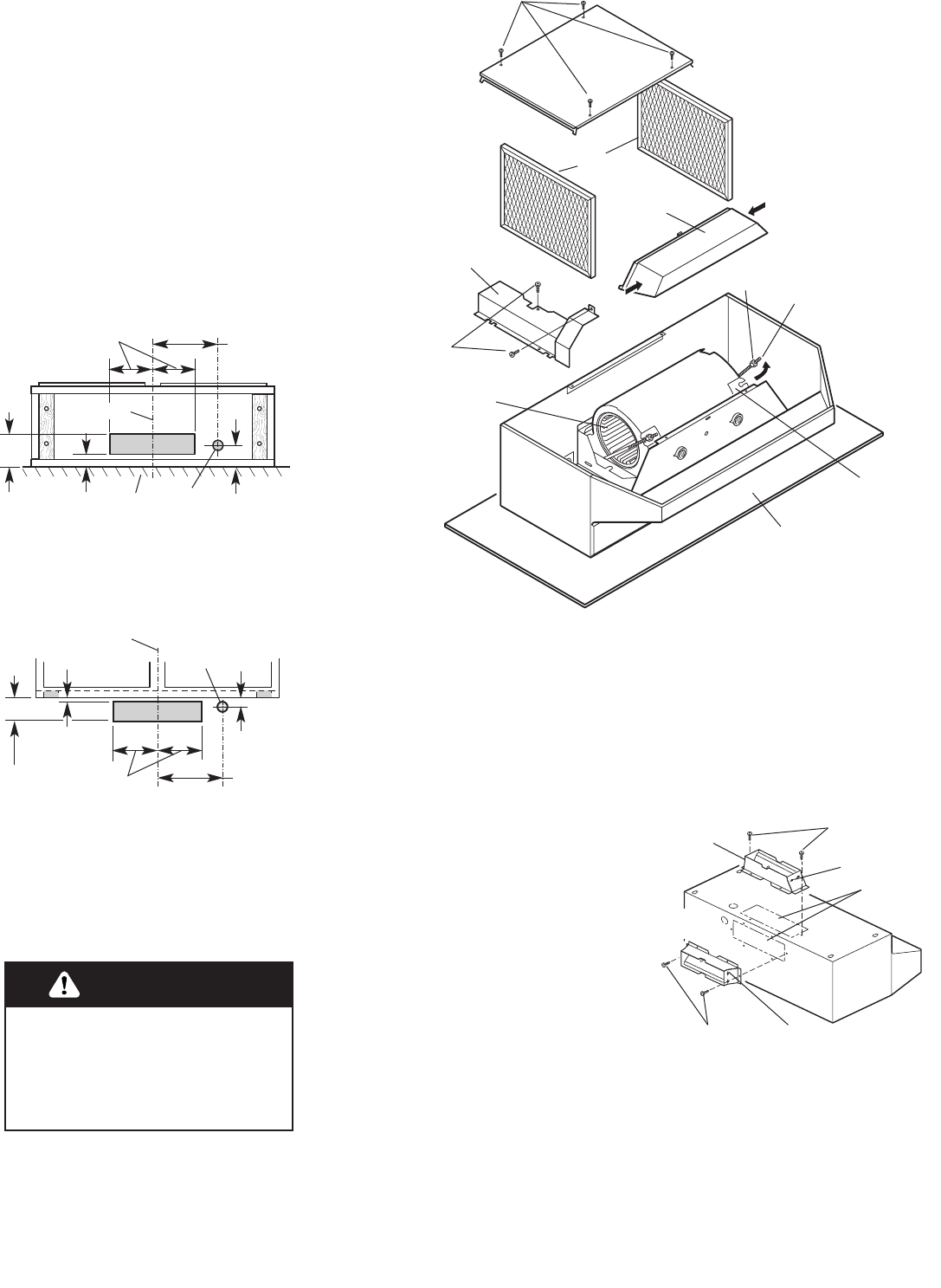
For Steps 5 through 10, refer to
Figure 3.
5.
Set hood upside down on a
protective covering such as
cardboard or large towel.
1-3/8"
(3.5 cm)
5-1/8"
(13.0 cm)
centerline
wall
6-1/4"
(15.9 cm)
7-1/2"
(19.1 cm)
2-1/8"
(5.4 cm)
1-1/4"
(3.2 cm)
dia. hole
3-1/4" x 10" (8.3 x 25.4 cm)
HORIZONTAL vent system
1/8"
(3.2 mm)
3-7/8"
(9.8 cm)
centerline
cabinet
front
6-1/4"
(15.9 cm)
7-1/2"
(19.1 cm)
3/4"
(19 mm)
1-1/4" (3.2 cm)
dia. hole
Excessive Weight Hazard
Use two or more people to move
and install range hood.
Failure to do so can result in
back or other injury.
WARNING
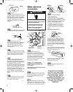
Figure 3
protective
cover
knurled
nut
mounting
rod
mounting
bracket
blower
assembly
blower
wheel
light
lens
filters
screws
bottom cover
wiring box
cover
screws
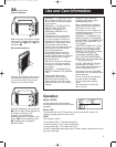
For vented installations, go to
Step 12a.
For non-vented installations,
go to Step 13.
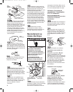
12a.
Depending on your
installation, remove either back or
top vent knockout.
12b.
Attach the
damper/vent connector to the
hood. Use the two black sheet
metal screws provided in the
parts bag. Note: If wall cap is
directly behind vent connector,
the dampers in the connector and
wall cap MUST NOT interfere
with each other. Remove the vent
connector damper if they
interfere.
6.
Remove bottom cover
screws and bottom cover.
7.
Remove filters.
8.
Remove wiring box cover
and screws.
9.
To make the hood lighter
and easier to install, it is
recommended that the blower
assembly be removed.
To remove:
a) Disconnect blower wiring
plug.
b) Loosen, but do not remove,
knurled nuts on mounting
rods. Slip rods out of blower
mounting brackets.
Important: Do not grasp blower
by blower wheels. Wheels may
be damaged.
c) Lift blower out and set aside.
10 .
Remove light lens.
Squeeze sides of lens toward
center to free lens tabs and lift
lens out.
11.
Depending on your
installation, remove either back or
top wiring knockout.
black
screws
black screws
horizontal
vent
vertical
vent
vent
knockouts
hinge pin
hinge pin
YL20380/8285188 6/17/02 2:55 PM Page 5