


the broil element. Set the oven
seledor and oven temperature control
knobs to “BROIL:‘The too element should
glow red and Indicate light should
beon.
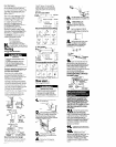
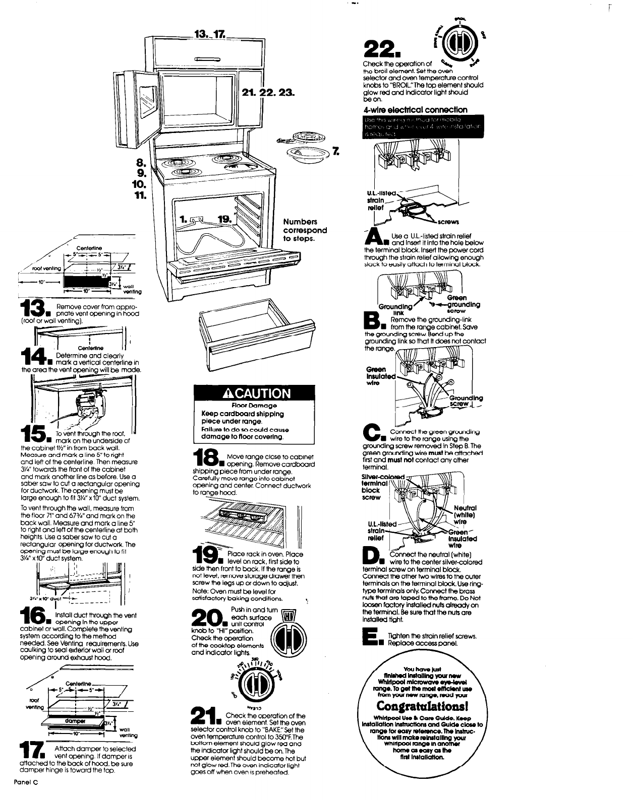
kwlre electrical connection
11.
:
nd
Use a U.L.-listed strain relief
n
and Insert it into the hole below
the terminal block. Insert the paver cord
through the strain relief allowing enough
slack to easily attach to terminal block.
t---.-
13
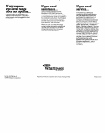
Remove cover from appro-
n
prtate vent opening in hcod
(roof of wall ventinat.
- -’
Gs---7-?I
‘1’
14.
T CenLne II I
.
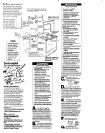
Determine and clearly
mark a vertical centerline in
the grounding screw.Bend
up the
grounding
link so that It does not contact
the area the vent opening will be made.
the range.
Floor Damage
Keep cardboard shipplng
piece under range.
FoIlurn to do so could cause
damage to floor coverlng.
C
LA--
Connect the green grcunding
W wire to the range using the
grounding screw removed In Step B. The
green grounding wire
must
be attached
;;tmi~lmust not contact any other
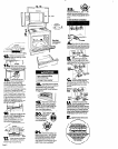
TOY&~ thr&gh the roof. jd
mark on the underside of
the cabinet IYz” in from back wall.
Measure and mark a line 5’to right
and left of the centerline Then measure
W” towards the front of the cabinet
and mark onother line as before. Use a
saber saw to cut a rectangular opening
for ductwork. The opening must be
large
enough
to fit 3Y4” x lo” duct system.
To vent through the wall, measure from
the floor 71” and 67%” and mark on the
back wall. Measure and mark a line 5”
to right and left of the centerline at both
heights. Use a saber saw to cut a
rectangular opening for ductwork The
opening must be large enough to fit
3Y4” x IO” duct system.
Move range close to cabinet
n
ODenina. Remove cardboard
shipping piece from under ranae
Careful& move range into cab:net
openina and center. Connect ductwork
to range hood
I
&nect the neutral (white]
wire to the center silvercolored
ace rack in oven.
Place
Vet on rack, first side to
side then front to back. If the ranae is
terminal screw on terminal block.
Connect the other two wires to the outer
terminals on the terminal block. Use rirg-
Npe terminals only Connect the brass
nuts that am taped to the tram-e. Do Not
kznsen factory installed nuts already on
the terminal. Be sure that the nuts are
installed tight.
E
Tighten the strain relief screws.
n
Replace access panel.
not level, remove storage drawerthen
screw the legs up or down to adjust.
Note: Oven must be level for
satisfactory baking conditions,
3v&y-&i+s
I
I__- ---__/
16
W
Install duct through the vent
opening In the upper
cabinet or wall. Complete the venting
system according to the method
needed See Venting requirements. Use
caulking to seal exterior wall or roof
opening around exhaust hood.
20
Push in and turn
n
knob to “HI” posttion.
Check the operation
of the ccoktop elements
and indicator lights
21
*1.72
n
Check the operation of the
oven element. Set the oven
selector control knob to “BAKE:‘Set the
oven temperature control to XW.The
bottom element should glow red and
the indicator light should be on The
upper element should become hot but
not glow redThe oven indicator light
goes off when oven IS preheated
WhMpoolmlcmwaveeys-kvel
mnQ0.10getthernaslonktentuae
homyourmwrange.roodpur
range far easy mfemnce. me lmhuc.
tloru will make mlrutalllng your
WMtpool range In another
llameasoasyaafhe
nd
Installation.
17---=-
Attach damper to selected
n
vent opening. If damper IS
attached to the back of hood, be sure
damper hinge is toward the top,
Panel C