


8
7. Remove the casters and fasteners from the box.
8. Locate and remove the caster brackets from the FeaturePak.
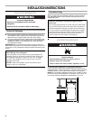
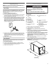
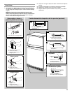
9. Using ⁵⁄₁₆–18 x ⁷⁄₈” hex-head bolts, attach one rigid caster and
one swivel caster to each caster bracket. The rigid caster fits the
front of the bracket and the swivel caster fits on the rear.
10. Insert the hex-head bolts from the bottom and start the self-
locking nuts for each caster.
11. Hold the head of the hex-head bolts with a wrench while
tightening the self-locking nuts with a socket wrench.
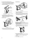
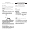
12. Using a ¹⁄₂" socket wrench, remove the four unit bolts (two on
each side) from the lower front and rear of the refrigerator.
NOTE: Do not remove leveling bolt.
Lower Front Corner
13. Place the slot in the rear of the caster bracket over the unit hole
in the rear of the refrigerator. Align the hole in the front of the
caster bracket with the unit hole in the front of the refrigerator.
Lower Rear Corner
14. Hold the bracket in place and insert the unit bolts into the front
and rear unit holes and tighten.
NOTE: Do not overtighten the bolts.
15. Insert two of the ¹⁄₄–20 x 1¹⁄₄" hex-head bolts and lock washers
into the two holes in the side of the caster bracket. Push the
caster bracket against the bottom of the refrigerator and tighten
the bolts using a ³⁄₈" socket wrench.
16. Repeat steps 12–14 for the other caster bracket.
Complete the Installation
1. Lock the front casters.
NOTE: Locking the casters will help prevent the refrigerator from
moving while it is being lifted.
2. Insert a small piece of cardboard between the caster brake and
the floor. This will help prevent the brake from rubbing on the
floor.
3. Stand the refrigerator upright.
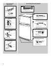
4. Replace the base grille by placing the metal clips in the openings
in the metal panel and rolling the grille downward until it snaps
into place.
5. Unlock the casters and move the refrigerator into its final
location.
6. Lock the casters.
7. Plug in refrigerator or reconnect power.
A. Self-locking nut
B. Caster bracket
C.
⁵⁄₁₆
–18 x
⁷⁄₈
" Hex-head bolt
D. Caster
A.
Leveling bolt (do not remove)
B. Unit bolt
B
A
C
D
A
B
A. Rear unit hole
B. Caster bracket
A. Caster bracket holes
A
B
A