RGH 8300-l '%
. .
RGHt!S3m-25
TO INSTALL RANGE HOOD
This unit can be vented vertically through uoper cabine!s or
horrzontally through an outside wall. A typical vertical installet~on iS
shown in Figure 1. A ryolcal horizonial rnstallatron IS shown In Figure
2. For proper ventila:ron when used wrth an indoor electrrc grill. see
paoe 2 for gurctelines for proper auct sizing. Improper duct sizing or
ins:alletion of restrictive roof jacks can reduce air moving capacity
and provide inadequate ventilation for an indoor electric grill. For
mcst efficient smoke removal, the top of the hood should be
approximately 56 Inches (13T.6 cm) from the floor.
1. Make a template or transfer measurements shown in Fig. 3 to
cabinets or wall.
2. Cut holes to accomodate ventilating duct allowing ‘4” (-6 cm)
clearance on all 4 srdes for back vent. Allow !.” (1.9 cm) clearance
toward front for vertical vent. A!low I%” (.6 cm) on other3 sides for top
vent.
3. Cut appropriate hole for electrical wiring.
4. Run wire through wall or cabinets according to Nattonal
Electrical Code and applrcable local codes. (DO NOT turn power on
until installation is complete.)
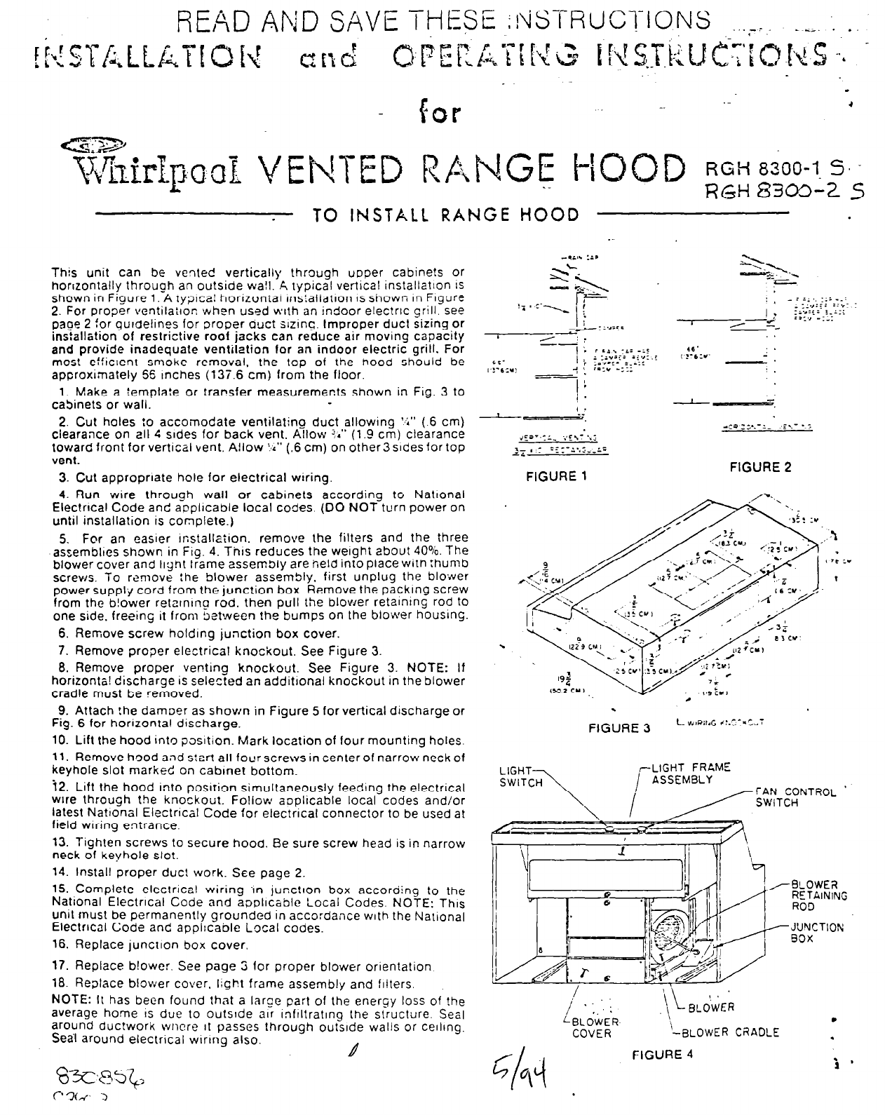
5, For an easrer rnstallaiion. remove the filters and the three
assembltes shown in Frg. 4. Thus reduces the weight about 40%. The
blower cover and light frame assembly are held into place with thumb
screws. To romove the blower assembly, first unplug the blower
power supply cord f:om the junction box. Remove the packing screw
from the b!ower retarnrno rod. then pull the blower retalntng rod to
one side. freeing it from between the bumps on the blower housing.
6. Remove screw holding junction box cover.
7. Remove proper electrical knockout, See Figure 3.
8. Remove proper venting knockout. See Figure 3. NOTE: If
horizonta! discharge is selected an additronal knockout in the blower
cradle must be removed.
9. Attach !he damoer as shown in Figure 5 for vertical discharge or
Fig. 6 for horizontal discharge.
10. Lift the hood into position. Mark location of four mounting holes.
11. Remove hood and start all four screws in center of narrow neck of
keyhole slot marked on cabmet bottom.
72. Lift the hood into posrrion simultaneously feeding the electrical
wire through the knockout. Fojlow aoplicable local codes and/or
latest Nattonal Electrrcal Code for electrical connector to be used at
field wiring entrance.
13. Tighten screws to secure hood. Be sure screw head is in narrow
neck of keyhole slot.
14. Install proper duct work. See page 2.
16. COmplete electrical wiring -in junction box according to the
National Electrical Code and applicable Local Codes. NOTE: This
Unit must be permanently grounded in accordance with the National
Electrical Code and applrcable Local codes.
16. Replace junction box cover,
17. Replace blower. See page 3 for proper blower orientation
18. Replace blower cover. light frame assembly and filters.
NOTE: It has been found that a large part of the energy loss of the
average home IS due to outslde air InfIltratIng the structure, Sea)
around duc!work wncre It passes through outside walls or ceilrng.
Sea-l around electrical wrrrng also.
L4
FIGURE 2
.
.
FIGURE 3
L V,lPil,G -,:.r,:*=w;
,-LIGHT FRAME
\
i
"I
,/-9LOWER
RETAINING
ROD
- J’JYCTION
90x
.
COVER
-BLOWER CRADLE
.
FIGURE 4


