


1
2
3
4
5
6.
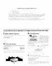
7
8
9
10
11
12
13
14
15
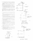
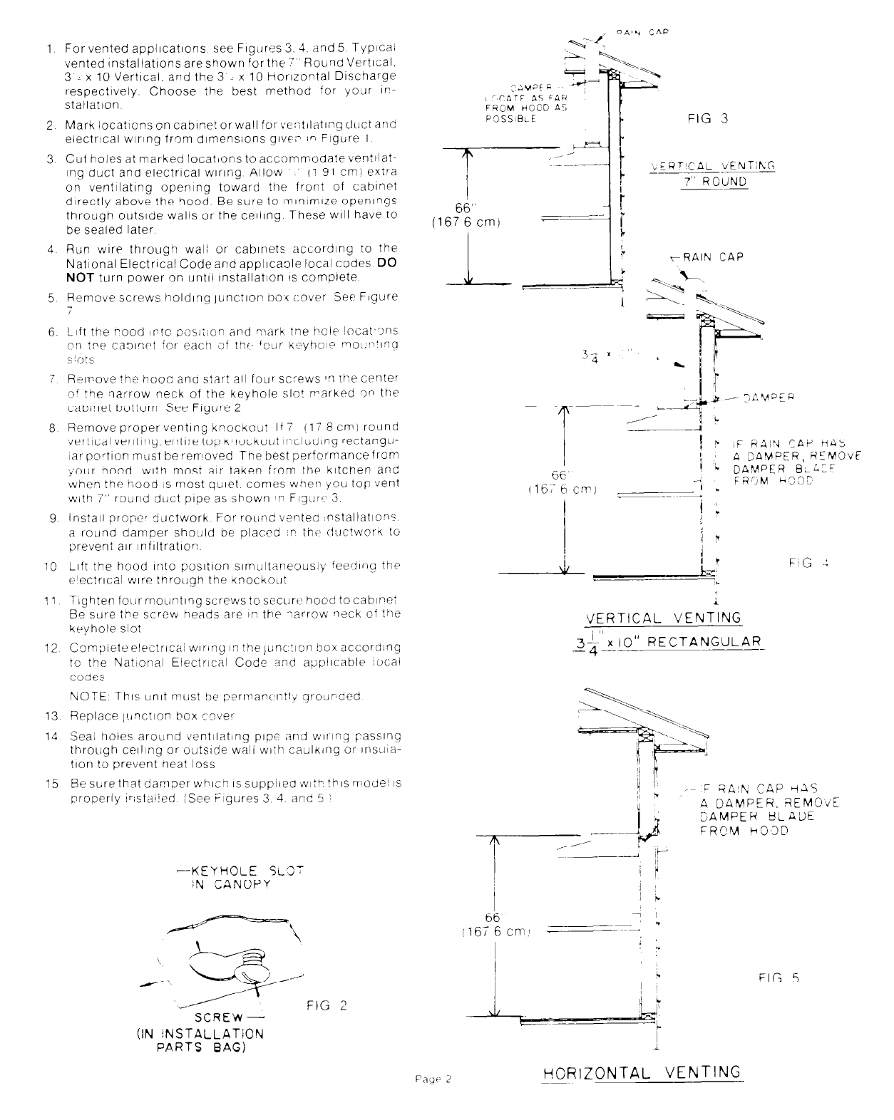
For vented appllcatlons see Flgllres 3. 3. And 5 Typica;
vented lnstallatlons areshown forthe Round Vertical.
3 : x 10 Vertical. and the 3 x 10 Horlzorltal Discharge
respectively Choose the best method for your IP-
stallatlon
;ivat F
LCCATE AS FAH
FROM HCjOD A:
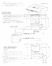
Mark locatIons on cabinet or wall for;,e:itllatlng duct and
electrIcal wiring from dlmenslons give:- in Figure 1
Cut holes at marked locatIons to accommodate venttlat-
mg duct and electrlcal wlrlng Allow
” (1 91 cm) extra
on ventilating opemng toward the front of cabinet
directly above the hood Be sure to lnlnlmlze openlrlgs
through outslde walls or the celling 7-hese WIII have to
be sealed later
Run wire through
wali
or cabinets according to the
National ElectrIcal Code and appllcaole local codes DO
NOT turn power on untW Installation IS complete
Remove screws holding )unctlor- noi cover Set Figure
H;IVOV~ ?he hoot ana star? all
foyer
screws II rhe CPnter
of the Iiarrow neck of the keyhole :;lo! rrarkpd ,on the
cabinet bottom See Figure 2
Remove proper venting kpocitout If 7 (17 8 cm1 round
\ier?ical venting, entire top Knockout tncludlng rectangle-
,ar portion mast be rerrloved The best perfor-mancefrom
);our hood with most air taken from the kltcnen and
when the hood IS most quiet. comes whep you top vent
with 7” round dL)ct pipe as shown #n F~qur’ 3
Install proper :jLJCtwork For round venteo nstaltations
a [round damper should ne placed ,P thi> iiI.lctworn to
prevent air infIltratIon
Lift the hood Into posItIon slmclltaneously feedIng the
e’ectrlcal wire through the knockoLlt
TIghten four moLlntlng screws to securt’ hood to cabirTn:
Be sure the screw heads are in the larrow r?;ck of the
keyhole slot
Completeelectrica~ wlr-ing n?he~unc!ion boxaccorolng
to the National Elect~cal Code and applicable xxal
Codes
NOTE Th!s umt must be permani’r:tIY qrourded
Replace jlinction box c‘over
Seal holes around tientilating
pipe
and
wlrg
passl’ig
through ceiling or outslde willi with caulking or InsLIla-
tlon to prevent heat loss
Be sLre that damper which IS suppiiec &I:P this niode! IS
properly lristalied iSee Figures 3 4 and 5 :
-KEYHOLE SL’IT
iN CANOPY
FIG ?
SCREW-
(IN iNSTALLATiON
PARTS BAG)
FIG 3
.ERTICAL VENTihG
------.
7” ROilND
-~~
rRAlh CAP
i
VERTICAL VENTING
3$‘rio” RECTANGULAR-
FIG 5
HORIZONTAL VENTING