


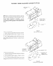
5. For an easier installation, remove the filters and the
Three assemblies shown in Fig. 9. This reduces the weight
about 40% The blower cover and light frame assembly are
held into place with thumb screws To remove the blower
asembly. first unplug the blower supply cord from the
junction box Remove the packrng screw from the blower
retaining rod, then pull the blower retarnrng rod to one srde.
freeing it from between the bumps on the blower housing
6. Remove screw holding junction box cover.
7. Remove proper electrical knockout. See Figure 1.
8. Remove proper venting knockout. See Fig. 1. NOTE: If
horizontal discharge is selected, an additronal knockout In
the blower cradle must be removed.
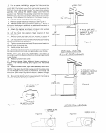
9. Attach the damper as shown in Figure 5 for vertical
discharge or Fig. 6 for horizontal discharge.
10. Lift the hood into position. Mark location of four
mounting holes.
11. Remove hood and start all four screws in center of
narrow neck of keyhole slot marked on cabinet bottom.
12. Lift into position on four screws simultaneously feeding
electrical wire through knockout.
13. Tighten screws to secure hood. Be sure screw head is in
narrow neck of keyhole slot.
14. Install proper duct work
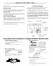
15. Complete electrical wiring In junction box according to
the national Electrical Code and applicable Local Codes.
NOTE: This unit must be permanently grounded in
accordance with the National Electrical Codeand applicable
Local Codes.
16. Replace junction box cover.
17. Replace blower. Note different blower positions in
Figure 7 for vertical venting and Figure 8 for horizontal
venting.
18. Replace blower cover, light frame assembly and filters.
NOTE: It has been found that a large part of the energy loss
of the average home is due to outside air infiltrating the
structure. Seal around ductwork where it passes through
outside walls or ceiling. Seal around electrical wiring also.
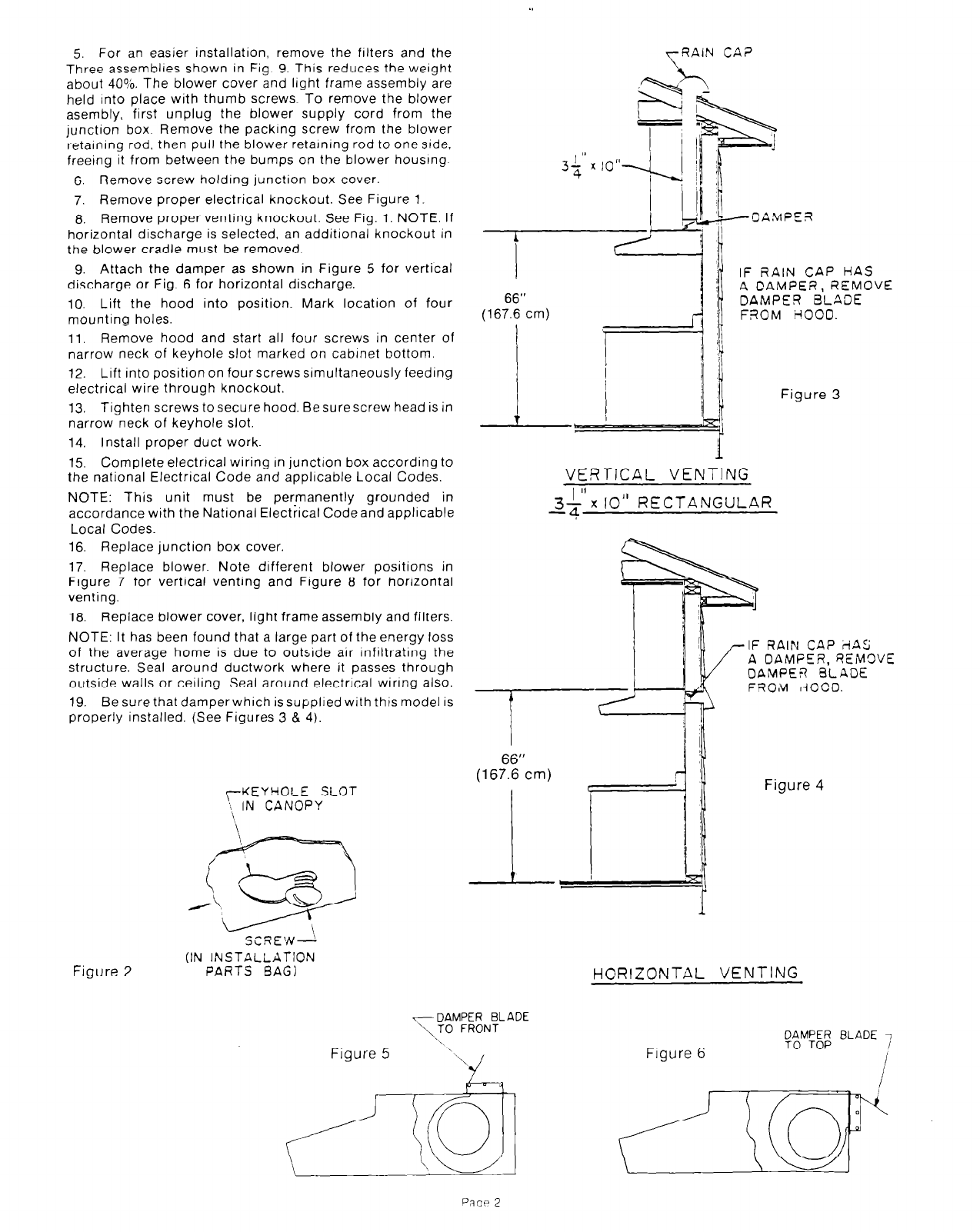
19. Be sure that damperwhich issuppliedwith this model is
properly installed. (See Figures 3 8 4).
rKEYHOLE SLOT
‘\ IN CANOPY
yQAlN CA?
I,
(167666 cm)
VERTICAL VENTING
2;’
x IO” RECTANGULAR
Figure 2
SCREW--!
(IN INSTALLATION
PARTS BAG)
r DAMPER BLADE
Figure 5
IF RAIN CAP HAS
A CAMPER, REMOVE
DAMPER BLADE
FROM HOOD.
Figure 3
RAIN CAP iiAS
DAMFEQ, QEIMOVE
MPE-R BLADE
OM ~i000.
Figure 4
HORIZONTAL VENTING
Figure 6
PRCIP 2