


INSTALLATION IJNDEQ KITCHEN F’JFQ ‘I)O’i’!Y
1.
For easy, one man I-staliation hood should be
disassembled.
First, remove the aluminum filter from fan box
assembly by pulling tab toward opposite end of
filter.
Remove two mount ng screws fcund in fan box
near back. (Figure :.)
Unplug power supply cord connection near
back.
Remove additional four screws from fan box
assembly and lift assembly out.
iisrnode tour scret.cs nolcrng top to canopy
assem biy
2.
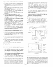
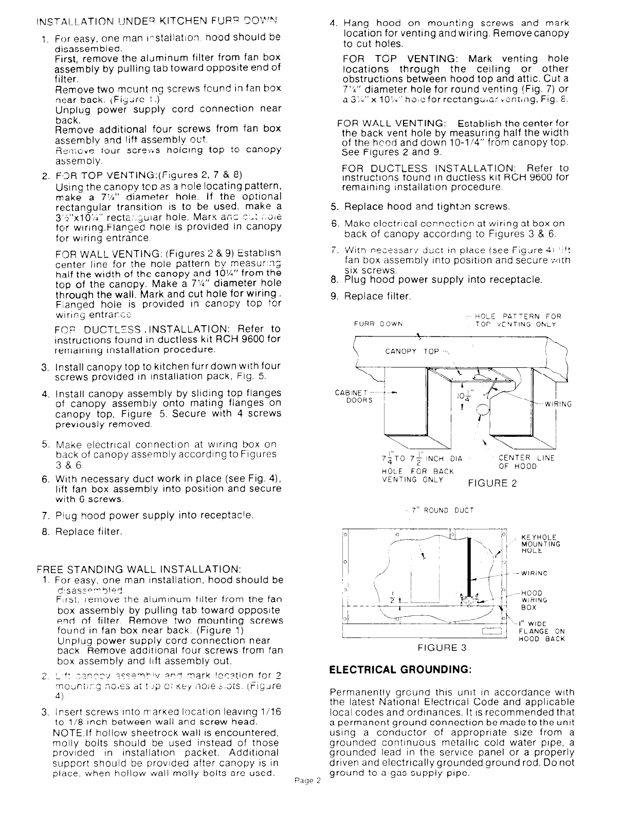
Fa3R TOP VENTING:(Figures 2, 7 8 8)
Using the canopy ?oo as a hole !ocating pattern,
make a 7’/4” diameter hole. If the optional
rectangular transition is to be used, make a
3’b”xlO’;;” rectz:.juirar hole. Mark an- c*: ,.;;e
for wrring.Flanged hole is provided in canopy
for wiring entrance
FOR WALL VENTING: (Figures 2 & 9) Establish
center line for the hole pattern by measur’ng
half the width of the canopy and 10%” from the
top of the canopy. Make a 7%” diameter hole
through the wall. Mark and cut hole for wlrlng
F!anged hole is provided in canopy top for
wiring entrant
3.
FCP DUCTLfSS , INSTALLATION: Refer to
InstructIons found in ductless kit RCH 9600 for
remarnrng installation procedure.
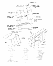
Install canopy top to kitchen furr down with four
screws provided in installation pack, Fig. 5.
4. Install canopy assembly by sliding top flanges
of canopy assembly onto mating flanges on
canopy top, Figure 5. Secure with 4 screws
prevrously removed.
5.
Make electrical connection at wiring box on
back of canopy assembly according to Figures
3&6
6.
With necessary duct work in place (see Fig. 4),
lift fan box assembly into position and secure
with 6 screws.
7.
Plug hood power supply into receptacle.
8. Replace filter.
FREE STANDING WALL INSTALLATION:
1. For easy, one man Installation, hood should be
:+sassnm5ls<
First, remove the aluminum tilter from tne fan
box assembly by pulling tab toward opposite
end of filter. Remove two mounting screws
found in fan box near back. (Figure 1)
Unplug power supply cord connection near
back Remove additional four screws from fan
box assembly and lift assembly out.
? I *I
i. -
y,pTr“,, “C’T-!hli, ,ap.-J
mark lorytion for 2
:r;OainiI:-.g
no,55 dt r ii;’ c: <(t-y I1oie -,3is. i,i!;Jre
4)
3. Insert screws Into n-arkea location leaving l/l6
to l/8 inch between wall and screw head.
NOTE:lf hollow sheetrock wall
IS
encountered,
molly bolts should be used instead of those
provided In installation packet. AddItional
support should be provided after canopy is in
place, when hollow wall molly bolts are used.
4.
Hang hood on mounting screws and mark
location for venting and wiring. Remove canopy
to cut holes.
FOR TOP VENTING: Mark venting hole
locations through the ceiling or other
obstructions between hood top and attic. Cut a
7’6” diameter hole for round venting (Fig. 7) or
a 3;;” x 10’,q” h~,e for rectanglr,a-,,~nili:g, Fig. 8.
FOR WALL VENTING: Establish the center for
the back vent hole bv measurina half the width
of the hood and down 1 O-1/4” from canopy top.
See Figures 2 and 9.
5.
6.
Replace hood and tighten screws
Make electrical connection at wiring at box on
back of canopy according to Figures 3 & 6.
7.
Witn nec?ssar:/ duct tn place (see Figure 4; ‘*rt
fan box assembly into posrtion and secure >,*ylth
six screws.
8. Plug hood power supply into receptacle.
9.
Replace filter.
FOR DUCTLESS INSTALLATION: Refer to
instructions found in ductless kit RCH 9600 for
remaining installation procedure.
FUAR DOWN ~-
-~ HOLE PATTERN FOR
TOP VENTING ONLY
F
CANOPY TOP ~-\
DOORS ~
7;‘TO 7;‘lNCH DIA
CENTER LINE
HOLE FOR BACK
OF HOOD
VENTING ONLY
FIGURE 2
7” ROUND DUCT
KEYHOLE
MOUNTING
HOLE
HOOD
WIRING
--4 ‘-1” WIDE
1
LIZ
FLANGE ON
HOOD BACK
FIGURE 3
ELECTRICAL GROUNDING:
Permanently ground this unit in accordance with
the latest National Electrical Code and applicable
local codes and ordrnances. It is recommended that
a permanent ground connection be made to the untt
using a conductor of appropriate size from a
grounded continuous metalltc cold water pipe, a
grounded lead in the service panel or a properly
driven and electrically grounded ground rod. Do not
Page 2
ground to a gas supply pipe.