


9
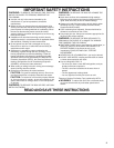
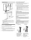
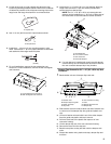
2. Lift the range hood up under cabinet and determine final
location by centering beneath cabinet. Mark on the underside
of cabinet the location of the 4 keyhole mounting slots on the
range hood. Set range hood aside on a covered surface.
3. Use ¹⁄₈" (3 mm) drill bit and drill 4 pilot holes as shown.
4. Install the 4 - 4.5 mm x 13 mm mounting screws in pilot
holes. Leave about ¹⁄₄" (6.4 mm) space between screw heads
and cabinet to slide range hood into place.
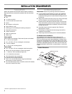
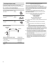
5. For roof installations, remove the top rectangular vent
knockout. For wall installations, remove the rear rectangular
vent knockout.
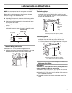
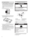
6. Install the 3¼" x 10" (8.3 x 25.4 cm) vent damper. Attach to
range hood with the 3.5 x 9.5 mm screws provided and
remove tape from damper flap.
NOTE: The 3¹⁄₄" x 10" (8.3 x 25.4 cm) rectangular vent
damper can be installed up to 1" (2.5 cm) on either side of
the hood center to accommodate off center ductwork.
■ If a vent damper is installed with a wall cap with damper,
check that they do not interfere with each other. Remove
the vent connector damper flap if they interfere.
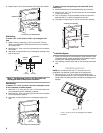
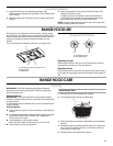
Damper Flap Removal for 3¼" x 10" (8.3 x 25.4 cm) Vent
Connector
1. Bend retainer wire out of damper flap catch tab.
2. Slide retainer wire to the side to allow one end of retainer wire
to come out of the damper flap wire guide and plastic end
cap.
3. Lift end of retainer wire and slide it out of the other damper
flap wire guide and plastic end cap to remove.
4. Push the small end of the plastic end caps out of vent
connector housing.
5. Lift the damper flap out of the vent connector housing.
6. Remove the foam from the stop tab.
7. Bend the stop tabs so they are flush with the damper side
walls.
8. Discard the retainer wire, plastic end caps, damper flap and
the foam.
A. Keyhole slot
A. Drill pilot hole.
A. Top rectangular vent knockout
B. Rear rectangular vent knockout
A
A
¹⁄₄"
(6.4 mm)
A
B
A. Vertical damper
B. 3.5 x 9.5 mm screws
C. Vent knockouts
D. Horizontal damper
A. Retainer wire
B. Damper flap wire guide
C. Plastic end caps
D. Stop tabs
E. Vent connector housing
F. Fo am
G. Damper flap catch tab
H. Damper flap
A
B
C
B
D
A
B
C
D
E
F
G
H