


10
5. Close the broiler door.
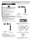
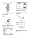
6. Remove cooktop burner caps and grates from parts
package. Align notches in burner caps with pins in burner
base. Burner caps should be level when properly positioned.
If burner caps are not properly positioned, surface burners
will not light. Place burners, burner caps and grates on the
cooktop.
7. Plug into a grounded 3 prong outlet.
Verify Anti-Tip Bracket Location
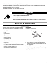
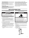
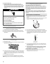
1. Check that the anti-tip bracket is installed:
■ Look for the anti-tip bracket securely attached to the floor.
■ Slide the range back so the rear range foot is under the anti-
tip bracket.
Level Range
1. Place rack in oven.
2. Place level on rack and check levelness of range, first side to
side; then front to back.
3. If range is not level, pull range forward until rear leveling leg is
removed from the anti-tip bracket. Use ³⁄₈" drive ratchet and
wrench or pliers to adjust leveling legs up or down until range
is level.
4. Push range back into position.
5. Check that rear leveling leg is engaged in anti-tip bracket.
NOTE: Range must be level for satisfactory baking performance.
Electronic Ignition System
Initial lighting and gas flame adjustments
Cooktop and oven burners use electronic igniters in place of
standing pilots. When the cooktop control knob is turned to the
“LITE” position, the system creates a spark to light the burner.
This sparking continues until the control knob is turned to the
desired setting.
When the oven control is turned to the desired setting, a hot
surface igniter heats to a bright orange and ignites the gas. No
sparking occurs. The glow bar remains on while the burner
operates.
Check Operation of Cooktop Burners
1. If control panel and knobs were removed earlier, reinstall
knobs.
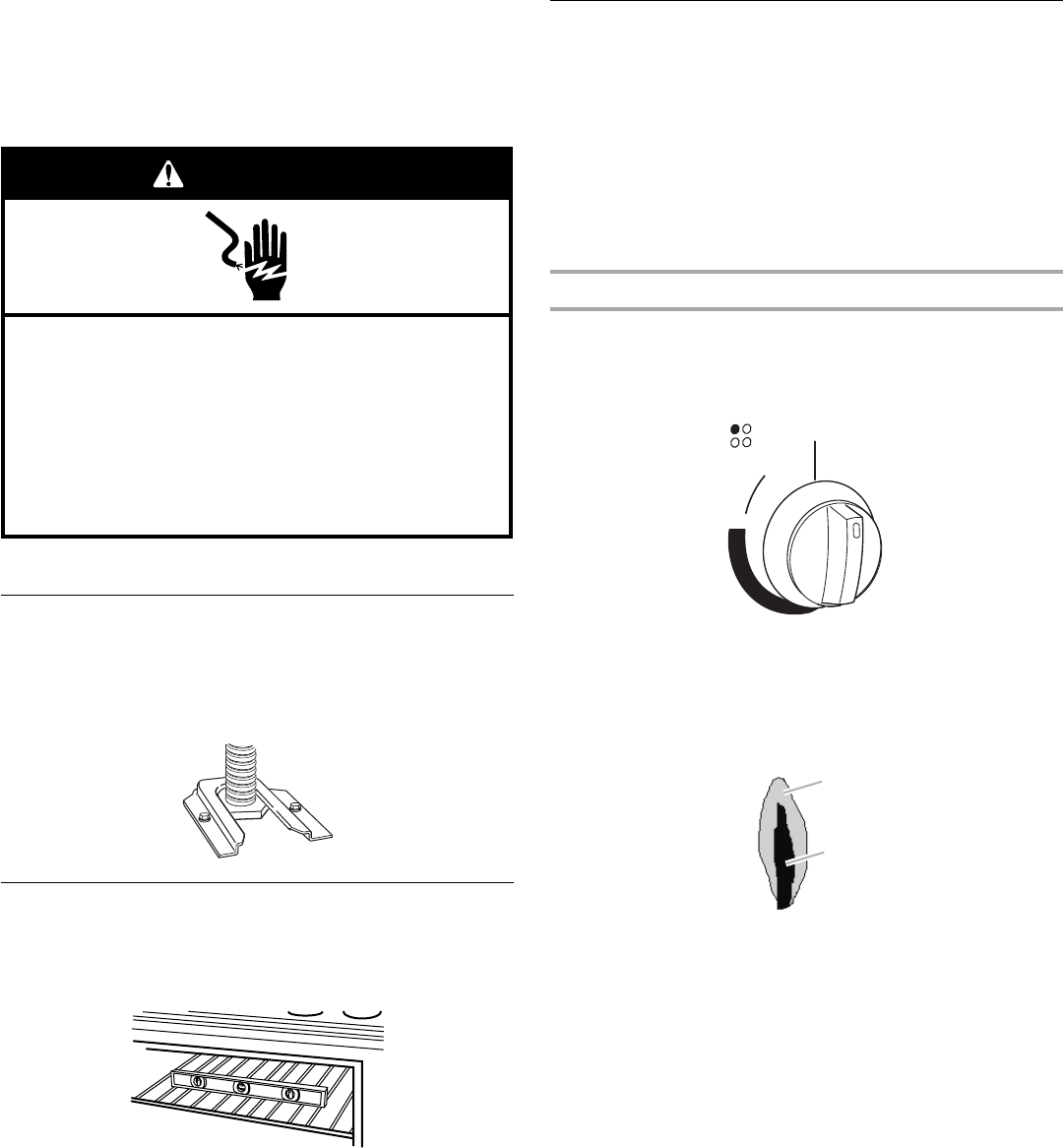
2. Push in and turn each surface unit control knob to the “LITE”
position. The flame should light within 4 seconds.
3. Turn control knob to the “HI” position after burner lights.
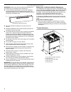
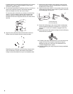
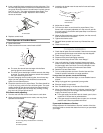
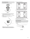
4. Check each cooktop burner for proper flame. The small inner
cone should have a very distinct blue flame ¼" (0.64 cm) to
½" (0.13 cm) long. The outer cone is not as distinct as the
inner cone.
5. Turn the control knob quickly to the “LO” position after the
burner lights. If the flame goes out, turn the control knob to
the “OFF” position.
6. Check each cooktop burner for proper low flame. The low
flame should be a minimum, steady blue flame. The flame
size should be ¼" to ³⁄₈" (0.64 cm to 0.95 cm) high.
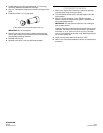
If the low flame needs adjusting:
1. With the burner flame on, turn control knob to the “Lo”
setting and remove control knob.
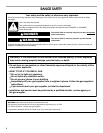
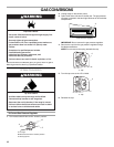
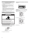
Electrical Shock Hazard
Plug into a grounded 3 prong outlet.
Do not remove ground prong.
Do not use an adapter.
Do not use an extension cord.
Failure to follow these instructions can result in death,
fire, or electrical shock.
WARNING
A.Outer cone
B.Inner cone
O
F
F
LO
LITE
MED
H
I
A
B