


4
Parts needed
For direct wire installation
■ UL listed or CSA approved ¹⁄₂" (12.5 mm) strain relief
■ 75-watt max incandescent light bulb
■ Power supply cable (if needed, for direct wire installation)
For power supply cord installation
■ UL Listed Power Supply Cord Connection Kit marked for
range hood use.
■ 75-watt max incandescent light bulb
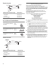
For vented installations you also need:
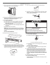
■ 3¹⁄₄" x 10" (8.3 x 25.4 cm) or 7" (17.8 cm) round metal venting
■ 7" (17.8 cm) round damper, if using 7" (17.8 cm) round vent
system
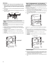
For cabinets with recessed bottoms:
■ Two 2" (5.1 cm) wide filler strips. Length and thickness
determined by recess dimensions.
■ Four flat head wood screws or machine screws with washers
and nuts (to attach filler strips).
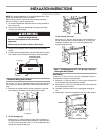
Location Requirements
IMPORTANT: Observe all governing codes and ordinances.
■ It is the installer’s responsibility to comply with installation
clearances specified on the model/serial rating plate. The
model/serial rating plate is located inside the range hood on
the rear wall.
■ Range hood location should be away from strong draft areas,
such as windows, doors and strong heating vents.
■ Cabinet opening dimensions that are shown must be used.
Given dimensions provide minimum clearance. Consult the
cooktop/range manufacturer installation instructions before
making any cutouts.
■ Grounded electrical outlet is required. See “Electrical
Requirements” section.
■ The hood is factory-set for vented installations. For non-
vented (recirculating) installations, charcoal filter pad Part
Number 4378581 is available from your dealer.
■ All openings in ceiling and wall where range hood will be
installed must be sealed.
For Mobile Home Installations
The installation of this range hood must conform to the
Manufactured Home Construction Safety Standards, Title 24
CFR, Part 328 (formerly the Federal Standard for Mobile Home
Construction and Safety, title 24, HUD, Part 280) or when such
standard is not applicable, the standard for Manufactured Home
Installation 1982 (Manufactured Home Sites, Communities and
Setups) ANSI A225.1/NFPA 501A*, or latest edition, or with local
codes.
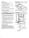
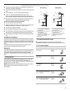
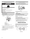
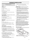
Product Dimensions
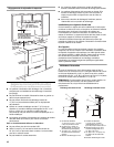
Installation Clearances
7
¹⁄₂
"
(19.1 cm)
2"
(5.1 cm)
1
¹⁄₂
"
(3.8 cm)
1"
(2.5 cm)
1
¹⁄₂
"
(3.8 cm)
6"
9"
(22.9 cm)
12"
(30.5 cm)
³⁄₄
"
(1.9 cm)
³⁄₈
"
(9.5 mm)
17
¹⁄₂
"
(44.5 cm)
29 ⁷⁄₈" (75.9 cm) - 30" (76.2 cm) model
35 ⁷⁄₈" (91.1 cm) - 36" (91.4 cm) model
(15.2 cm)
18" (45.7 cm)
min. clearance
upper cabinet
to countertop
36" (91.4 cm)
base cabinet
height
13" (33.0 cm)
cabinet depth
30" (76.2 cm) or
36" (91.4 cm) min.
cabinet opening width
18"(45.7 cm) min.
24" (61.0 cm)
suggested max.
bottom of cabinet
to cooking surface