


3
INSTALLATION REQUIREMENTS
Tools and Parts
Gather the required tools and parts before starting installation.
Read and follow the instructions provided with any tools listed
here.
Tools needed
Parts needed
Check local codes and consult gas supplier. Check existing gas
supply and electrical supply. See “Electrical Requirements” and
“Gas Supply Requirements” sections.
Location Requirements
IMPORTANT: Observe all governing codes and ordinances. Do
not obstruct flow of combustion and ventilation air.
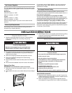
■ It is the installer’s responsibility to comply with installation
clearances specified on the model/serial rating plate. The
model/serial rating plate is located at bottom front face
surface on the right-hand side of the oven frame.
■ The oven should be located for convenient use in the kitchen.
■ Recessed installation area must provide complete enclosure
around the recessed portion of the oven.
■ All openings in the wall or floor where oven is to be installed
must be sealed.
■ Cabinet opening dimensions that are shown must be used.
Given dimensions provide minimum clearance with oven.
■ Grounded electrical supply is required. See “Electrical
Requirements” section.
■ Proper gas supply connection must be available. See “Gas
Supply Requirements” section.
IMPORTANT: To avoid damage to your cabinets, check with your
builder or cabinet supplier to make sure that the materials used
will not discolor, delaminate or sustain other damage. This oven
has been designed in accordance with the requirements of UL
and CSA International and complies with the maximum allowable
wood cabinet temperatures of 194°F (90°C).
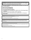
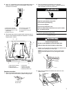
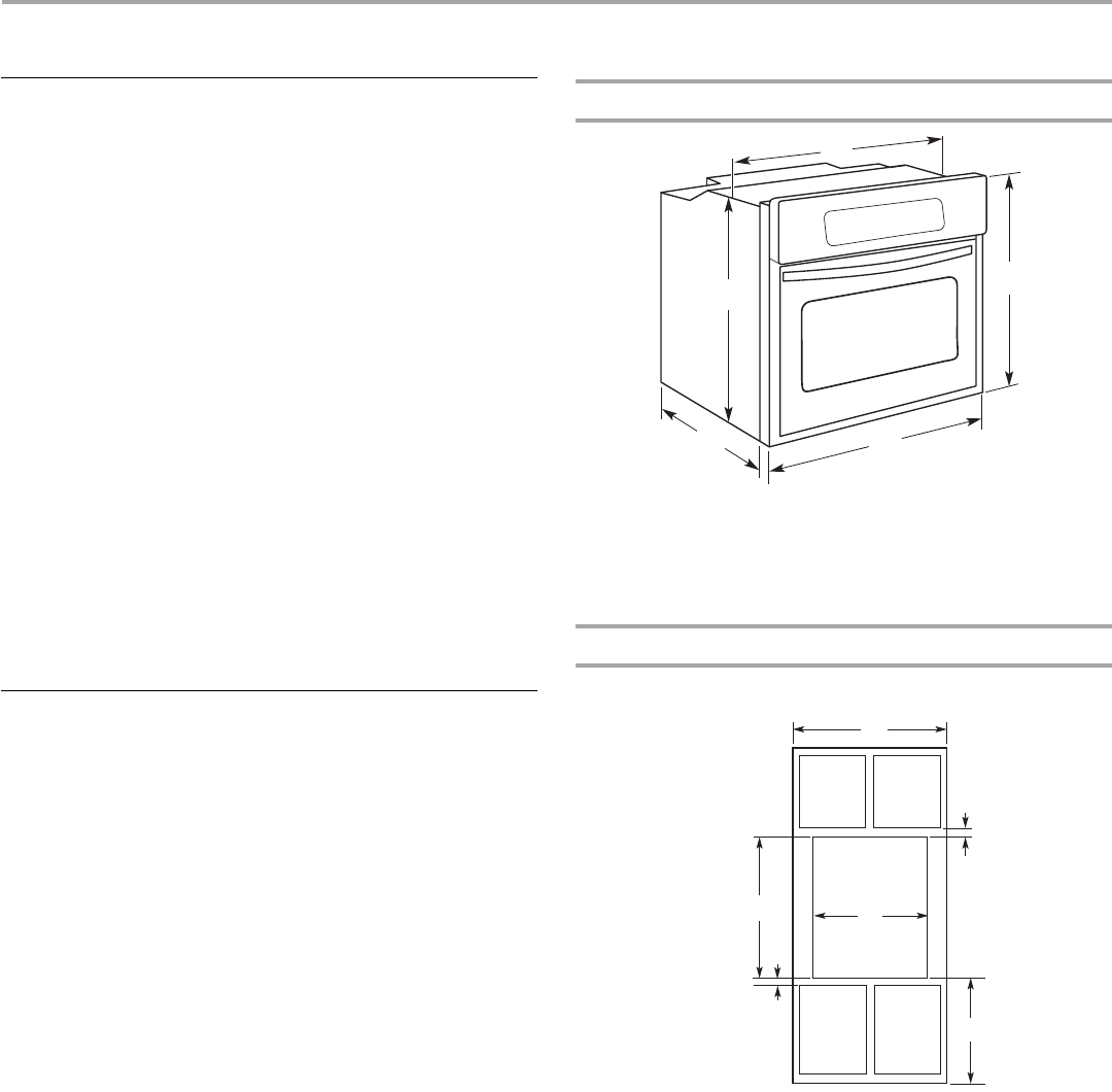
Product Dimensions - Single Oven
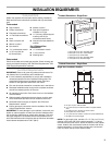
Cabinet Dimensions - Single Oven
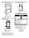
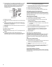
Single Oven Installed in Cabinet
NOTE: For gas supply pipe, provide a 3" x 3" (7.6 cm x 7.6 cm)
opening in the back wall of the cabinet centered 7" (17.8 cm)
from the left rear corner and 3" above the bottom of the cabinet
cutout. Install a 120 volt electrical outlet in the back wall of the
cabinet centered 6" (15.2 cm) from the right rear corner and 4"
(10.2 cm) below the top of the cabinet cutout.
■ Tape measure
■ Phillips screwdriver
■ Flat-blade screwdriver
■ ¹⁄₈" Flat-blade screwdriver
■ Level
■ Hand or electric drill
■ Wrench or pliers
■ Pipe wrench
■ ¹⁵⁄₁₆" combination wrench
■ ¹⁄₈" (3.2 mm) drill bit
(for wood floors)
■ Marker or pencil
■ Pipe-joint compound
resistant to LP gas
■ ³⁄₁₆" (4.8 mm) carbide-tipped
masonry drill bit (for
concrete/ceramic floors)
■ Noncorrosive leak-detection
solution
For LP/Natural Gas
Conversions
■ ½" combination wrench
■ 7 mm nut driver
■ Masking tape
A.22¹⁄₄" (56.8 cm) max. recessed width
B.39¹⁄₄" (99.7 cm) max. overall height
C.23⁷⁄₈" (60.6 cm) overall width
D.22⁵⁄₈" (57.5 cm) max. recessed depth
E.37³⁄₄" (95.9 cm) recessed height
A.24" (61 cm) min. cabinet width
B.1¹⁄₂" (3.8 cm) top of cutout to bottom of upper cabinet
door
C.14" (35.6 cm) min. bottom of cutout to floor
D.22³⁄₈" (56.8 cm) cutout width
E.1¹⁄₂" (3.8 cm) min. bottom of cutout to top of cabinet door
F. 38" (96.5 cm) cutout height
A
B
C
D
E
A
B
C
D
E
F