


2
WIRING
SETTING THE DIAL
All wiring must conform to local and national electrical codes and ordinances.
Connect in accordance with wiring diagrams provided by the equipment manufacturer. If none are provided, the following
represents a typical installation.
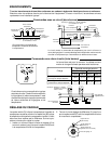
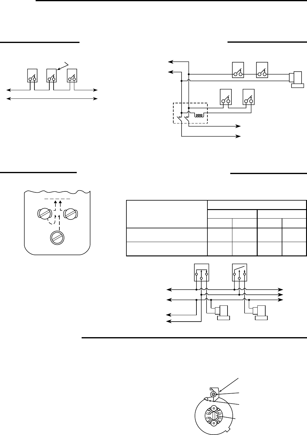
The movable indicator (D) points to the temperature at which the
compressor starts. The fixed indicator (B) points to the tempera-
ture at which the compressor will stop. The difference between
these two indicators is the differential. Follow these instructions
to set the dial:
1. Insert a screwdriver in the adjusting slot (A) and turn the dial
until the fixed indicator (B) points to the temperature at which
the compressor is to stop.
Temperature
control
Low
temperature
limit
High side
pressure control
(if used)
To
Compressor
Motor
Line
L1
L2
Note:Make L1 “HOT” on
120V installation
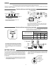
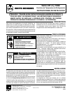
Circuit showing temperature control con-
trolling compressor directly.
Temperature
control
Low temperature
limit
Suction
pressure
control
High side
pressure
control
Motor
starter
Solenoid
refrigerant
valve
To
Compressor
Motor
Line
L1
L2
Note:Make L1 “HOT” on
120V installation
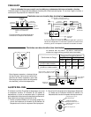
Circuit showing temperature control to open and close
refrigerant valve. Suction pressure control starts and stops
compressor through motor starter.
“B” Fixed indicator
(cut-out point)
“C” Differential
adjusting screw
“D” Movable indicator
(cut-in point)
“A” Adjusting
slot
Controls with one circuit (two terminals)
Controls with two circuits (three terminals)
BLUE
RED
WHITE
240V
22.2A
22.2A
LOAD CONDITIONS
MAXIMUM ALLOWABLE RATING
Full Load Locked Rotor
120V
7.4A
7.4A
120V
44.5A
44.5A
240V
3.7A
3.7A
Load between Blue and Red
terminals must not exceed:
Load between Blue and White
terminals must not exceed:
To
Additional
Units
B
R
W
B
R
W
Valve
No. 2
Valve
No. 1To
Compressor
Motor
Line
L1
L2
Note:Make L1 “HOT” on
120V installation
This diagram shows a typical two-circuit applica-
tion. Several zones receive refrigeration from the
same compressor, but each zone requires its
own solenoid refrigerant valve and temperature
control.
The blue terminal is common. The table below shows the
maximum load allowed between terminals.
2. Turn the differential adjusting screw (C) until the movable
indicator (D) points to the temperature at which the com-
pressor is to start.