


4
INSTALLATION (cont’d)
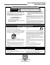
SYSTEM WIRING
To prevent electrical shock and/or equipment
damage, disconnect electrical power to system at
main fuse or circuit breaker box until installation
is complete.
All wiring should be installed in accordance with local
and national electrical codes and ordinances.
Always check that the electrical power supply used agrees
with the voltage and frequency shown on the gas control.
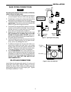
The typical wiring diagrams (figs. 3 & 4) show only the
terminal identification and/or wiring hook up. Always refer
to wiring instructions provided by Equipment Manufac-
turer for system hookup operation.
PILOT GAS ADJUSTMENT
If the pilot flame is low and does not engulf the bulb of the
mercury flame sensor, the system will not energize the
main valve. If pilot gas pressure is too high, gas will sputter
past the ignition electrode, and may not ignite. High pilot
gas pressure may also cause the flame to lift off the
burner, causing the flame sensor bulb to sense “low” heat.
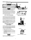
To adjust the pilot gas pressure, remove the cover screw
(see fig. 5). To REDUCE pilot pressure, turn the pilot
adjust screw (beneath the cover screw) clockwise. To
INCREASE pilot pressure, turn the pilot adjust screw
counterclockwise. Replace and tighten cover screw.
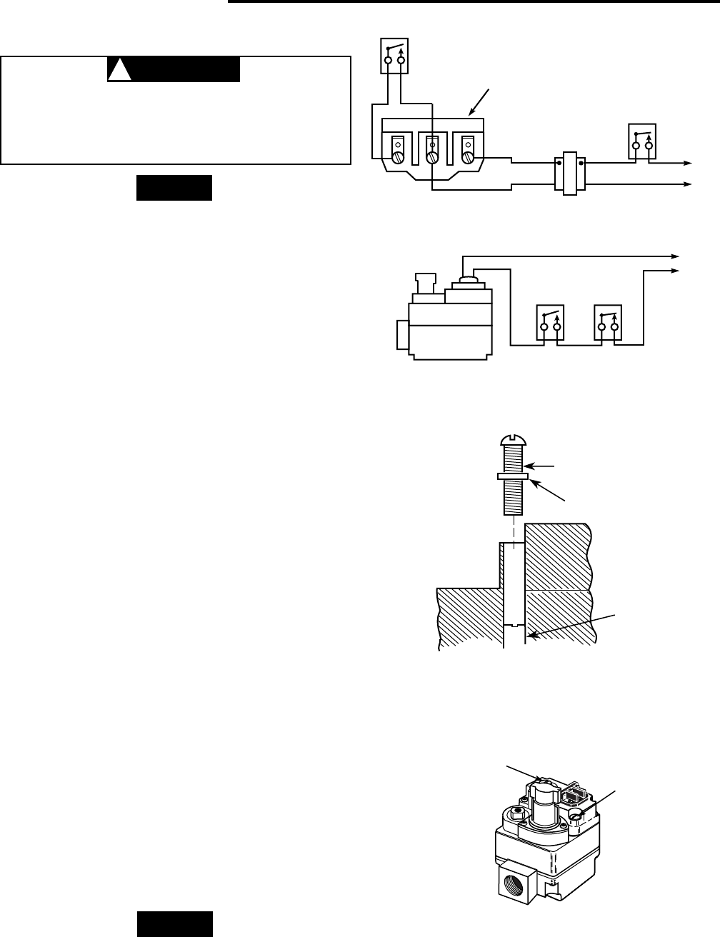
PRESSURE REGULATOR
ADJUSTMENT
The pressure regulator has been factory adjusted (see
control for specific setting). Although additional adjust-
ments will not normally be necessary, you may adjust the
regulator. Do not force the adjusting screw beyond the
limits that it can easily be adjusted.
1. Energize valve to ignite main burner.
2. Remove “Reg. Adj.” cover screw (see fig. 6).
3. To DECREASE outlet pressure, turn the adjusting
screw (beneath the cover screw) counterclockwise.
To INCREASE outlet pressure, turn the adjusting
screw clockwise.
4. Replace the cover screw. Cycle the valve two or three
times to verify regulator setting.
If adjustment to higher range (4.2” W.C. to 11.0” W.C.) is
required, use conversion kit packed with control.
NOTE
CAUTION
!
NOTE
Gas valve
terminal panel
Figure 3. Wiring for 36C01 (24 Volt)
TH TH-TR TR
LINE
High
limit
24 VAC
HOT
Transformer
Thermostat
Line voltage
operating
control
Line
Gas valve
High
limit
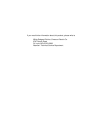
Figure 4. Wiring for 36C01A (120 Volt)
Pilot adjust
cover screw
Gasket
Pilot
adjust
screw
Figure 5. Pilot gas adjustment
Figure 6. Pressure regulator adjustment
OFF
PILOT
ON
Pilot adjust
cover screw
Regulator adjusting
cover screw