


3
CAUTION
!
INSTALLATION
MOUNTING AND WIRING
Do not use on circuits exceeding specified volt-
age. Higher voltage will damage control and
could cause shock or fire hazard.
To prevent electrical shock and/or equipment
damage, disconnect electric power to system at
main fuse or circuit breaker box until installation
is complete. Failure to earth ground the appli-
ance or reversing the neutral and hot wire con-
nection to the line can cause shock hazard.
Shut off main gas to heating system until instal-
lation is complete.
Route and secure all wiring as far from flame
as practical to prevent fire and/or equipment
damage.
Replace 50E47 control as a unit - no user serviceable
parts.
All wiring should be installed according to local and
national electrical codes and ordinances.
The 50E47 control may be mounted on any convenient
surface using two #6 x 5/8 sheet metal screws. If desired,
it is designed to be mounted on a 4" x 4" junction box using
two #8-32 x 5/8" machine screws.
The control must be secured to an area that will experi-
ence a minimum of vibration and remain below the maxi-
mum ambient temperature rating of 175°F. The control is
approved for minimum ambient temperatures of -40°F.
Any orientation is acceptable.
Refer to the wiring diagram and wiring table when con-
necting the 50E47 control to other components of the
system.
UL approved, 105°C rated 18 gauge min., stranded, 2/64"
thick insulation wire is recommended for all low voltage
safety circuit connections. Refer to 50E47 specification
sheet for recommended terminals to mate with those on
the control.
UL approved 105°C rated 16 gauge min., stranded,
4
⁄64”
thick insulation wire is recommended for all line voltage
connections. Refer to 50#47 specification sheet for rec-
ommended terminals to mate with those on the control.
Following installation or replacement, follow appliance
manufacturer's recommended installation/service instruc-
tions to insure proper operation.
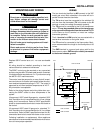
WIRING
The two terminals identified as MV connect to the 36E
model gas valve. Both solenoids in the valve will be in
parallel across these two terminals.
The TH terminal must be connected to the switched 24
volt wire from the thermostat (TH is the same as the W
terminal on most low voltage thermostat systems).
The TR terminal is connected to the 24 volt transformer
return. TR may be grounded either at the transformer
or by a ground wire extended from the terminal TR (TR
is the same as the C terminal on most low voltage
thermostat systems).
The L1 terminal and IGN terminal are connected with a
two-terminal connector on the ignitor leads.
The FP terminal is connected to the flame probe. Maxi-
mum recommended wire length to the flame probe is 36
inches.
The GND terminal is a ground and return path for the
flame sensor probe. GND must be reliably connected
to the burner chassis ground.
MV
MV
TR
TH
FP
GND
L1
IGN
Redundant
Valve
Main
Valve
HOT NEUTRAL
Limit
LINE VOLTAGE
Common (C)
50E47
Flame Sensor
Probe
Silicon Carbide
Ignitor
BLACK
WHITE
Thermostat
Transformer
24 VAC
60 Hz
Class II
WR
LINE VOLTAGE
LOW VOLTAGE
WARNING
!
NOTE