


9
CONTROL OPERATION
Each burner has an individual control knob allowing infinite heat selection between high and low.
- 9,000 Btu/hr burner adjusts to 1300 Btu/hr Low
- 12,000 Btu/hr burner adjusts to 1600 Btu/hr Low
- 15,000 Btu/hr burner adjusts to 2100 Btu/hr Low
- 18,500 Btu/hr burner adjusts to 4100 Btu/hr Low and 500 Btu/hr Ultra-Low
The control knobs are plated metal and can be removed (by pulling straight upward) for improved cleaning. Be sure the
control is in the OFF position before removing a knob. When cleaning in the area of the controls, use a damp cloth to
wipe surfaces only after cooktop has cooled. DO NOT USE CLOTHS THAT ARE SOPPING WET.
To operate a control, push down and rotate counter clockwise. The high heat position has a detent for easy selection. The
center burner control (CTG305D & CTG365D only) has detents at the HIGH, MEDIUM and LOW heat positions. The
controls rotate counter clockwise from OFF to LOW. Rotate the control knob clockwise to the full OFF position.
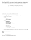
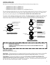
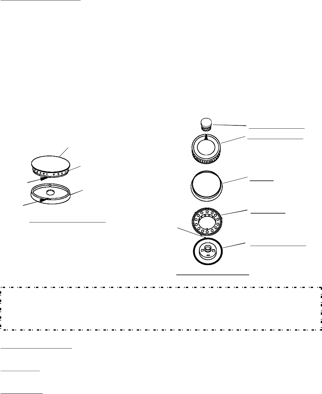
BURNER HEAD WITH
PROCELAIN CAP
GAS PORTS
BURNER BASE
TAB
NOTCH
SINGLE BURNER ASSEMBLY
(INSERT TAB INTO NOTCH)
HOLE
LOCATING
BURNER RING
INSERT BOTTOM PIN
ON BURNER HEAD INTO
HOLE IN BURNER BASE
(TOP VIEW)
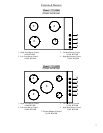
SKIRT
LOCATING PIN AND
NOTCH IN BURNER
RING ALIGNS WITH
IN BURNER HEAD
HOLE AND TAB
BURNER HEAD
SIMMER BURNER CAP
LOCATED IN COOKTOP
BURNER BASE
CENTER BURNER ASSEMBLY
FIG - 7
BURNER ASSEMBLY
Burners are sealed for easier cleaning.
Single Burner – The burner head has two locating tabs that fits into notches in the burner base (located in cooktop) For
proper burner operation the burner head tabs must be located in the burner base notches. See illustration.
Center Burner – On those models that have a center burner, the sequence of assembly and positioning of the
components is important for proper burner operation. The order of the assembly is – burner ring first, skirt next and
the burner head last. The simmer cap can be positioned in any sequence. The burner head and burner ring index with
pins, tabs and notches to indicate proper assembly. See illustration.
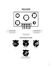
CAUTION: IMPROP
ER POSITIONING OF BURNER CAN DAMAGE COOKTOP AND CAUSE
INJURY TO PERSONS.
CORRECT POSITIONING RESULTS IN EVEN FLAME DISTRIBUTION AND
APPEARANCE.