


9
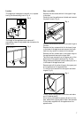
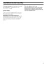
Check the position again by slackening the screws
and pins then, once the best position has been
obtained, fully tighten all the fixings.
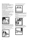
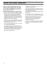
Cover the visible part of the top bracket on the
panel with plastic cover (D), inserting it in the
locations provided in the bracket.
Fig. 11
Once the door has ben correctly aligned, tighten the
holding nuts on the fixing brackets and attach the
appliance to the adjacent units and the bottom of
the work surface (Fig. 12).
Fig. 12
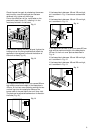
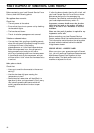
If the appliance has been fitted into a space 820 mm
high and the maximum height of the base plate is
100 mm, fit the front cover plate by pushing the two
vertical lugs into the rectangular holes on the
bottom side of the ventilation duct until they click.
The plate can be adjusted backwards or forwards in
the holes (Fig. 13).
Fig. 13
D472
D
D517
135
185
170
220
600
820
870
D518
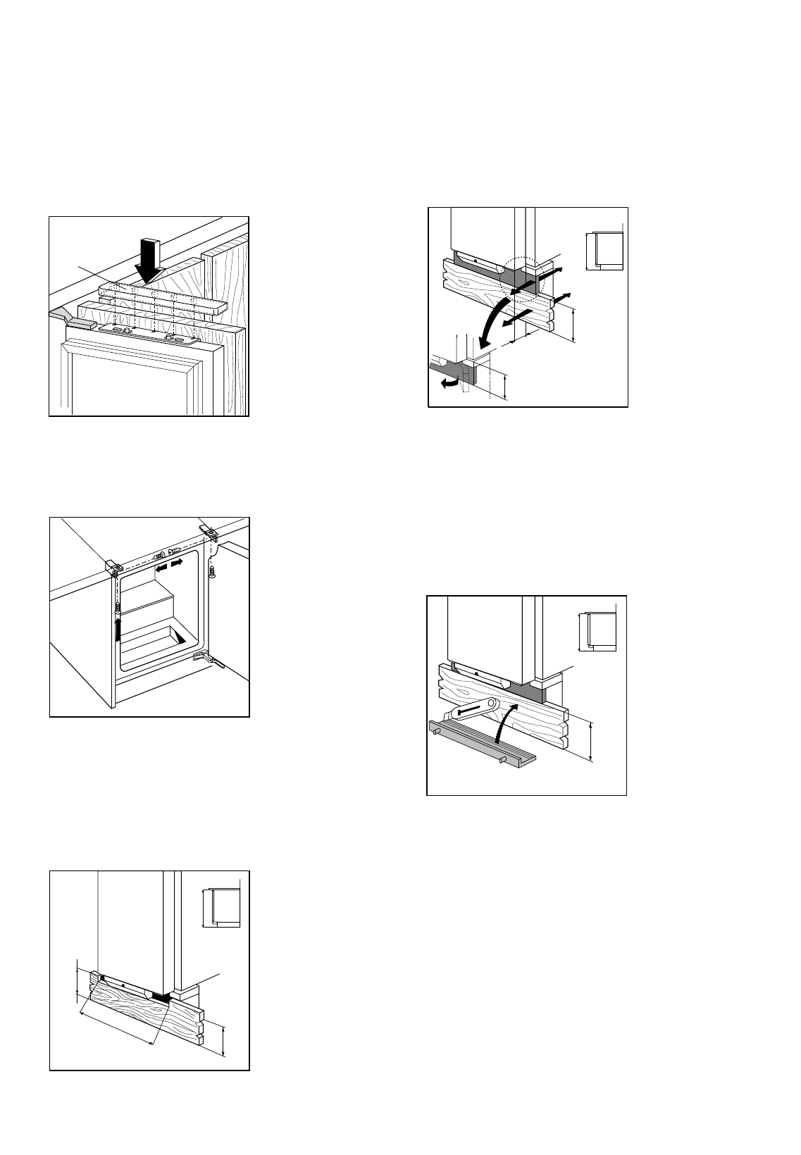
If the base plate is between 100 and 135 mm high,
cut it as shown in Fig. 15 and mount as described
above.
If the base plate is between 135 and 170 mm high,
cut it as shown in Fig. 13.
Fig. 14
If the appliance has been fitted into a space 870 mm
high and the maximum height of the base plate is
150 mm, fit the front cover plate as described in
Fig. 14.
If the base plate is between 150 and 185 mm high,
cut it as shown in Fig. 15.
If the base plate is between 185 and 220 mm high,
cut it as shown in Fig. 13.
Fig. 15
100
150
820
870
20÷80
D546
min.
50cm
2
100÷135
150÷185
820
870
D520