


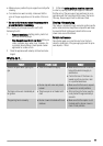
Adjustment of minimum level
To adjust the minimum level of the burners:
1. Light the burner.
2. Turn the knob on the minimum position.
3. Remove the control knob.
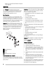
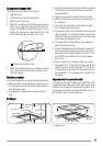
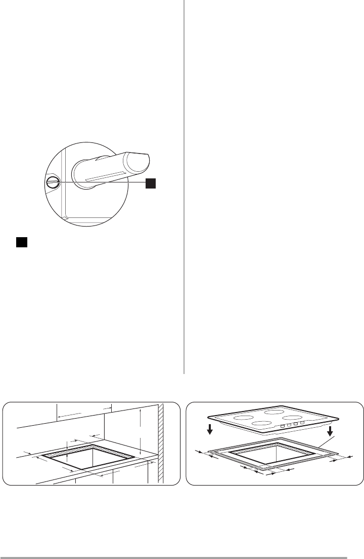
4. With a thin screwdriver, adjust the by-pass screw po-
sition. If you change from natural gas 20 mbar to liq-
uid gas, fully tighten the adjustment screw in. If you
change from liquid gas to natural gas 20 mbar, undo
the by-pass screw approximately 1/4 of a turn.
1
1
Minimum adjustment screw
5. Make sure the flame does not go out when you quick-
ly turn the knob from the maximum position to the
minimum position.
Electrical connection
• Ground the appliance according to safety precautions.
• Make sure that the rated voltage and type of power on
the rating plate agree with the voltage and the power of
the local power supply.
• This appliance is supplied with a mains cable and
plug.
• Any electrical component must be installed or replaced
by the Service Force Centre technician or qualified
service personnel.
• Always use a correctly installed shockproof socket.
• Make sure that there is an access to the mains plug af-
ter installation.
• Do not pull the mains cable to disconnect the appli-
ance. Always pull the mains plug.
• The appliance must not be connected with an extension
cable, an adapter or a multiple connection (risk of fire).
Check that the ground connection is in conformity with
the standard and regulations force.
• The power cable must be placed in such a way that it
does not touch any hot part.
• Connect the appliance to the mains with a device that
lets to disconnect the appliance from the mains at all
poles with a contact opening width of minimum 3 mm,
eg. automatic line protecting cut-out, earth leakage
trips or fuse.
• None of a parts of the connection cable can not get a
temperature 90°C. The blue neutral cable must be con-
nected to the terminal block label with "N". The brown
(or black) phase cable (fitted in the terminal block con-
tact marked with "L") must always be connected to the
live phase.
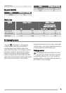
Replacement of the connection cable
To replace the connection cable use only H05V2V2-F T90
or equivalent type. Make sure that the cable section is ap-
plicable to the voltage and the working temperature. The
yellow/green earth wire must be approximately 2 cm lon-
ger than the brown (or black) phase wire.
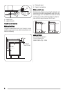
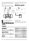
Building In
min. 55 mm
min. 650 mm
550 mm
min. 450 mm
30 mm
470 mm
min. 600 mm
10 mm
11 mm
11 mm
A
3 mm
A - supplied seal
5