


8
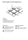
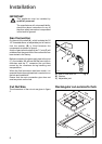
A) End of shaft with nut
B) Washer
C) Adjustable joint
Installation
IMPORTANT
This appliance must be installed by
qualified personnel.
The manufacturer will not accept liability,
should the above instructions or any of
the other safety instructions incorporated
in this book be ignored.
Gas Connection
On the end of the shaft (A) , which includes the GJ
1/2" threaded elbow, an adjustable joint is fixed so
that the washer (B) is fitted between the
components as shown in figure 4.
A drop of paint at both edges of the "L" joint (C) will
evidence that the good seal of the connection has
been tested in the factory.
Before connecting the gas supply pipe to the joint
(C), the installer will ensure that the paint drop is
unbroken and the "L" connector has not been
moved by the vibrations during handling and
transportation.
When the final connection has been made, it is
essential that a thorough leak test is carried out on
the hob and installation.
Ensure that the main connection pipe does not
exert any strain on the hob.
FO 1010
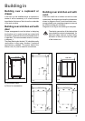
Cut Out Size
The dimensions of the cut-out are given in figure
5.
Rectangular cut-out size for hob
550
470
580
510
55 min.
FO 2340
SR
SR
R
A
Dimensions are given in millimeters
Fig. 4
Fig. 5