


37
Instructions for the Installer
The instructions given below are designed
specifically for a qualified installer and should
aid him or her to perform all installation,
adjustment, and maintenance operations with
absolute precision and in compliance with all
current legislation and regulations. We
strongly recommend that all operations for
the installation of your cooker be carryed out
by Qualified Personnel in accordance with
existing rules and regulations.
Electrical connection
Prior to making the electrical connection, make sure that:
— the protection fuse and the domestic wiring
system are suitable to carry the total electric load of the
oven (see rating plate);
— your domestic wiring system has an efficient
earth connection in compliance with rules and laws in
force;
— the wall socket or the omnipole switch used for
the electrical connection can easily be reached after the
oven is built in.
This appliance is delivered without an electric supply cable,
therefore, you will have to fit to it a supply cable with standard
plug, suitable for the total electric load shown on the rating plate.
The plug is to be inserted into a suitable wall socket. If you
require a direct connection to the electric network (mains), it will
be necessary to fit between the appliance and the mains an
omnipole switch, with a minimum gap between contacts of 3
mm, suitable for the required load and in compliance with rules
in force. The green & yellow ground wire must not be interrupted
by the switch, and should be 2-3 cm longer than the phase and
neutral wires. The supply cable must in all cases be laid out in
such a way as to ensure that it does not reach at any given
point a temperature 50°C higher than the ambient temperature.
Suitable power supply cables are the following types, considering
the respective necessary section of cable: H07 RN-F, H05 RN-
F, H05 RR-F, H05 VV-F, H05 V2V2-F (T90), H05 BB-F.
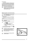
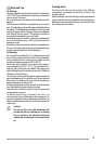
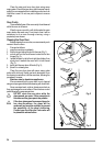
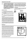
Terminal block
The oven is fitted with an easily accessible terminal
block (Fig. 8) which is designed to operate with a single-
phase power supply of 230 V.
Letter L - Live terminal
Letter N - Neutral terminal
or E - Earth terminal
Fig. 8
To ensure correct operation of the built-in assembly, the
kitchen cabinet and the recess for the built-in appliance must
have suitable dimensions. When the appliance is fitted-in,
there must be no open spaces left and it must be closed on
all sides by the kitchen furniture to prevent the possibility of
inadvertently touching “live” (current carrying) parts of the
oven. All parts ensuring such a protection, including any
covering panel (for instance, if the appliance is installed at the
end or at the beginning of a kitchen counter) must be fastened
in such a way as to prevent removal of the same without the
aid of some tool. This appliance can be placed with its back
and with one side close to appliances or walls of higher
height. The other side, instead, must be placed close to
furniture or appliances, having the same height.
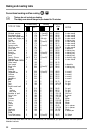
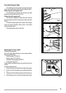
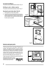
Overall oven dimensions (Fig. 9)
Building-in
Fig. 9