Table 5 E1/T1 Connections on each 50-pin Telco Connector
E1/T1 Number
1 to 8 9 to 16
Tx Pins (Tip/Ring) Rx Pins (Tip/Ring)
1 9 27/2 26/1
2 10 29/4 28/3
3 11 31/6 30/5
4 12 33/8 32/7
5 13 35/10 34/9
6 14 37/12 36/11
7 15 39/14 38/13
8 16 41/16 40/15
To connect E1/T1 trunk using RJ-48c connectors, follow these 2 steps:
1 Connect the E1/T1 trunk cables to the ports labeled Trunks 1 to 8 (in the case of the 8-
trunk device) on the V7122 RTM.
2 Connect the other ends of the Trunk cables to the PBX/PSTN switch.
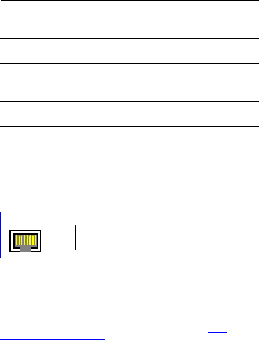
RJ-48c trunk connectors are wired according to
Figure 7.
Figure 7 Pinout of RJ-48c Trunk Connectors
1 2 3 4 5 6 7 8
3, 6, 7, 8
not connected
body = shield
1 = Rx Ring
2 = Rx Tip
4 = Tx Ring
5 = Tx Tip
RJ-48c Connector and Pinout
Installing the Ethernet Connection
Connect a standard Category 5 network cable to the Ethernet RJ-45 port (and the other as
optional redundancy/backup). Connect the other end of the Category 5 network cables to
your IP network. The Ethernet connectors (labeled Ethernet 1 and Ethernet 2) are wired
according to
Figure 8.
When you assign an IP address to the V7122 gateway using HTTP (under
Step 1 in Section
Assigning an IP Address Using HTTP), you may be required to disconnect this cable and re-
cable it differently.
18
V7122 Digital Gateway Installation Guide


