GB - 26
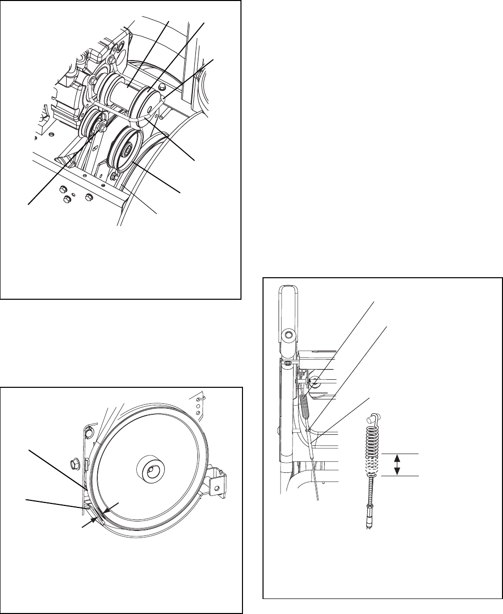
3. Check brake.
When the clutch lever is disengaged, the brake
must contact attachment belt.
When the clutch lever is engaged, the brake must
be more than 1/16 in. (1.6 mm) away from the
belt (Figure 31).
4. Repeat steps 1 – 3 until spring extension and
brake clearance are within specified range.
5. Check belt finger clearance (Figure 34).
With clutch lever engaged, belt finger on the side
opposite the belt idler should be less than 1/8 in.
(3 mm) from belt, but not touching the belt. Adjust
belt finger as necessary.
6. Replace bottom cover.
7. Replace belt cover.
TRACTION DRIVE CLUTCH ADJUSTMENT
If drive slips, adjust traction clutch to compensate for
friction disc wear.
To adjust traction clutch:
1. Place speed selector in fastest forward speed.
2. Place unit in service position.
3. Measure the length of the traction drive clutch
spring at the top of the traction cable. See Figure
32.
4. Engage and hold the traction drive clutch lever
and measure the spring again. The spring should
be 1/2 -11/16 in. (12.7-17.5 mm) longer when the
lever is engaged.
Figure 30
1.Engine Sheave
2.Attachment Drive Belt
3.Belt Finger
4.Attachment Belt Idler
5.Attachment Pulley
6.Attachment Idler
Adjustment Nut
OS7195
1
2
3
3
4
5
6
Figure 31
1.Drive Belt
2.Brake Shoe and Pad
OS7200
Minimum of 1/16 in.
(1.6 mm)
1
2
Figure 32
1/2 -11/16 in.
(12.7-17.5 mm)
1.Traction Drive Clutch Spring
2.Jam Nut
3.Adjuster Body
1
2
3
OS7205
OS7210
