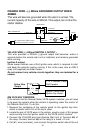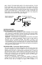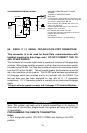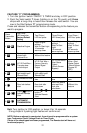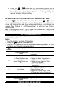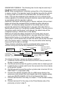
#H7. 16 PIN MOLEX CONNECTOR:
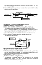
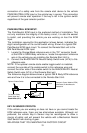
WIRING
Keep wiring away from moving engine parts, exhaust pipes and
high-tension cable. Be sure to tape wires that pass through holes on the
firewall to prevent fraying.
CAUTION: Do not connect the wire harness to the control module until
all wiring to vehicle is complete.
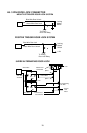
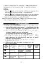
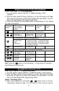
H1: 6 PIN HEAVY GAUGE WIRING CONNECTIONS:
Remember that what the system does to start a vehicle is to duplicate the
functions of the ignition key switch! Below, we will explain the three basic
functions of the ignition switch. Since this installation will require analysis
of the ignition switch functions, we recommend making the three
connections below at the ignition switch harness directly.
Violet Wire—Starter Output
Careful consideration for the connection of this wire must be made to
prevent the vehicle from starting while in gear. Understanding the
difference between a mechanical and an electrical Neutral Start Switch
will allow you to properly identify the circuit and select the correct
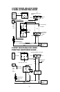
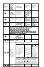
Orange
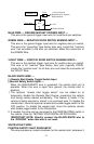
Wire: (-) 500mA Grounded Output When Armed
White / Violet Wire: (+) Brake Switch Shut Down Input
Black / White
Wire: (-) Neutral Safety Switch Input
Yellow
Wire: (-) 200mA Ignition 3 Control Output
Blue / Black
Wire: (-) 200mA Accessory 2 Control Output
Brown / Black
Wire: (-) 200mA Ground When Running Output
Wire: Tachometer Signal Input
White / Black Wire: (-) Negative Hood Pin Safety Shut Down
White Wire: (-) 200mA Dome Light Control Output
Gray
Wire: (-) 200mA Channel 2 (Trunk) Output
Pink
Wire: 2-Step Unlock(Fatory Default)/Factory Dsrm/Sensor By-pass
Gray / Black
Wire: (-) 200mA Starter 2 Output
1 2 3 4
5
6 7
8
9 10 11 12 13 14
15 16
Blue Wire:(-) Zone 2 Negative Hood/Trunk trigger
Green Wire : Zone 3 (-) Negative Door Pin Trigger
X
Violet Wire: Zone 3 (+) Positive Door Trigger