D-Command Guide16
Attaching the Units
To attach the D-Command Fader Module to the Main Unit:
1 Remove the plastic end cap from the left end of the Main
Unit.
2 Place the Fader Module to the left of the Main Unit, and
press the D-Command units together.
3 Slide both units forward far enough to have complete access
to the front bracket screw holes.
4 Attach the front bracket, using four 10-32 3/4-inch socket
cap screws.
5 Slide the connected units backwards far enough to have
complete access to the rear screws.
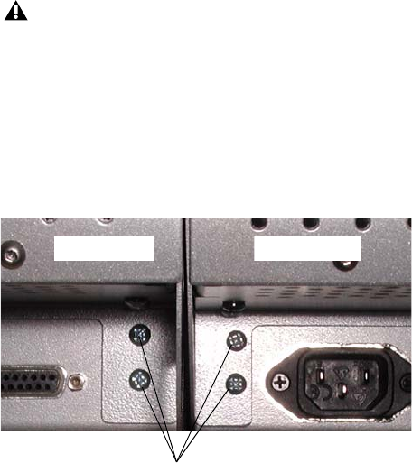
6 Remove the four Philips head screws indicated in Figure 4.
7 Attach the rear bracket, using four 10-32 3/4-inch socket cap
screws and four 6-32 x 3/8-inch Philips pan head screws.
8 Carefully slide the connected units forwards far enough to
have complete access to the center bracket screw holes.
9 Attach the center bracket, using two 10-32 3/4-inch socket
cap screws.
10 Press the D-Command units together. If necessary, use a
ratcheting nylon strap to press the units together by running
the strap around the two units. Make sure the nylon strap does
not contact any switches or encoders on the surface.
11 Tighten the bracket screws on the Fader Module.
12 Attach the plastic end cap to the Fader Module.
When bracketing together a D-Command system, leave all
screws on the Fader Module loose enough to allow you to ad-
just the position of the units relative to each other. After all
three brackets are installed, and the units are pressed fully
together, you will fully tighten the Fader Module screws.
Figure 4. Rear view of D-Command and Fader Module


