8
Cisco SFS 3504 Multifabric Server Switch Installation and Configuration Note
78-18335-01
Installing the Cisco SFS 3504 Server Switch
Note The least amount of protrusion for the adjustable brackets must be 1/2 inch beyond the inside end of the
guide rail. The adjustable bracket should always be fully supported by the guide rails.
Installing with the Data Connection Cables Flush-front
To install the Cisco SFS 3504 Server Switch on a rack so that the data connection cables are flush-front
on the rack posts, perform the following steps:
Step 1 Open the bag that contains the mounting hardware.
Note To mount a Cisco SFS 3504 Server Switch on a rack, use eight screws and eight rack nuts. These
must be supplied by the customer, based upon the compatibility of the screws and nuts with the
specific racks.
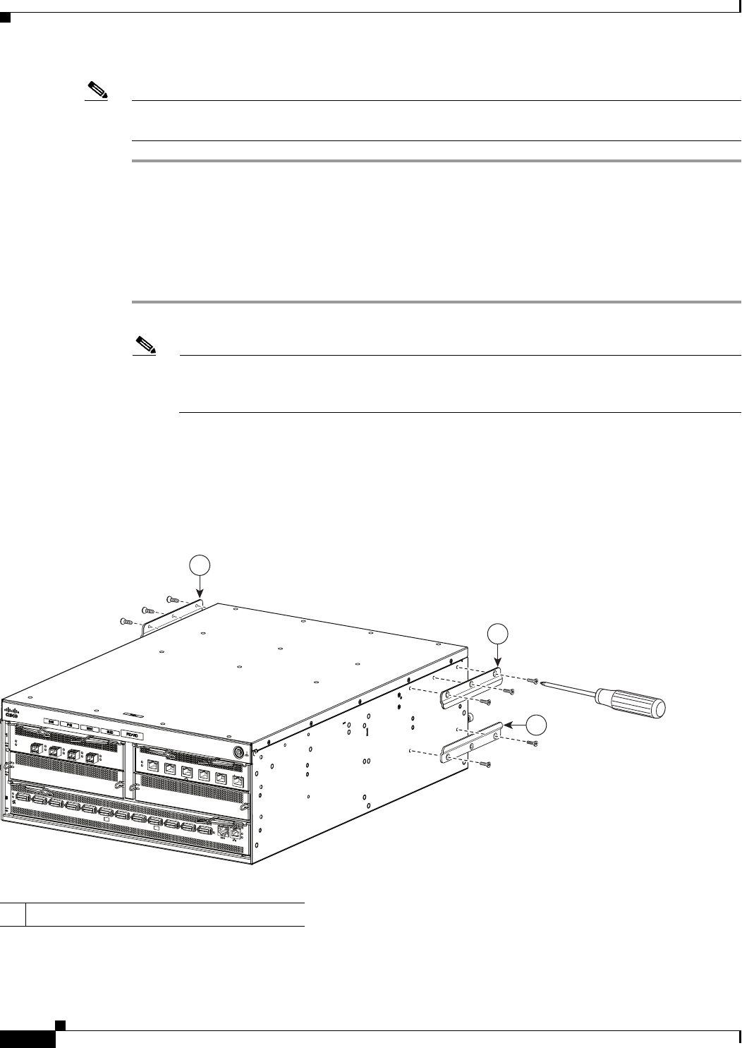
Step 2 Remove the two guide rails that are attached to either side of the Cisco SFS 3504 Server Switch at the
data-connection end, and attach the guide rails similarly at the power-fan modules end. (See Figure 3.)
Use a Phillips screwdriver to unscrew the guide rails, and secure them at the new locations with the
screws that you just removed.
Figure 3 Attaching Guide Rails at the Power-Fan Module End
1 Guide rails
250430
Cisco SFS3504 Multifa
bric Switch
!
O
K
1
2
3
4
5
6
7
8
9
1
0
1
1
1
2
T
X
/R
X
L
in
k
D
S
FS
350
0 S
eries FC
G
atew
ay
!
OK
1
2
3
4
Fault
Link
S
F
S
3
5
0
0
S
e
rie
s
E
th
e
rn
et G
a
te
w
a
y
!
O
K
1
2
3
4
5
6
T
X
/
R
X
L
in
k
1
0
0
/1
0
0
0
B
a
s
e
T
1
1
1


