SERVICE
MAINTAINING YOUR PUMP
Lubrication
It is not necessary to lubricate the pump or its motor• The motor
bearings are lubricated for life. The mechanical shaft seal in the
pump is water lubricated and selt:adjusting.
Draining for Winter
When the pump is to be disconnected from service, or is in dan-
ger of freezing, it must be drained. The pump has a draincock
which must be opened. Remove the priming plug to vent the
pump. Drain the pressure tank. Drain all piping to a point below
the freezing line.
To drain an air volume control (AVC), remove the tubing. Turn the
AVC upside down. This will permit any water to drain into tank.
Dis, assembly and Assembly of Pump
The Hydroglass* Pump is designed for ease in servicing and main-
tenance.
1. Disassemble pump as follows:
A Disconnect power.
B. Open faucet to relieve pressure.
C. Drain pump by opening draincock. Remove pressure switch
tubing from fitting on top of pump.
D. Remove clamp, Key No. lO, Page 11.
E. Remove pump base mounting bolts. Motor assembly and
back half assembly of pump can be pulled away from front
half.
F. Remove O-Rings.
2. Reassembly of pump.
A. Clean O-Rings and O_Ring grooves.
B. Lubricate O-Rings with petroleum jelly, and place in grooves•
C. Slide pump halves together.
D. Clean inside of clamp. Place clamp around pump halves.
Ahemately tighten clamp screw and tap clamp around out-
side with plastic mallet. This will insure proper seating of O-
; Ring and clamp.
E. Assemble base mounting bolts• Connect pressure switch tub
ing and close draincock.
F. prime pump and turn on power.
REMOVING MOTOR FOR SERVICE AND
REPLACING SHAFT SEAL
If it is necessary to remove motor, always replace the shaft seal. We
suggest you purchase this item, UIO9_A, and have it on hand for
future use.
NOTICE: The seal consists of two parts, a rotating member and a
ceramic seat. The surfaces of the seal are easily damaged. Read in-
structions carefully.
Remove motor as follows:
1. Disassemble pump per instructions above.
2. Remove diffuser and impeller as follows (Key Nos. 7 and 8, Page
10.
A. Remove ,_rews holding diffuser.
B. Loosen two screws and remove motor canopy.
C. If motor has capacitor, partially unscrew capacitor clamp and
move capacitor to one side•
e _
[AWARNINGJ Risk of electrical shock Do not touch ca-
pacitor terminals with body or any metal object.
D. Hold motor shaft with a 7/16" wrench on the shaft flats.
E. Turn impeller counterclockwise when facing it.
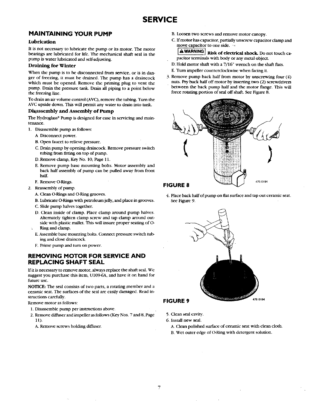
3. Remove pump back half from motor by unscrewing four (4)
nuts. Pry back half off motor by inserting two (2) screwdrivers
between the back pump half and the motor flange. This will
force rotating portion of seal off shaft. See Figure 8.
(
)
FIGURE 8
4750194
4. Place back half of pump on flat surface and tap out ceramic seat.
See Figure 9.
5. Clean seal cavity.
6. Install new seal.
A. Clean polished surface of ceramic seat with clean cloth•
B. Wet outer edge of O-Ring with detergent solution.
