Dell™ PowerEdge™ T610 Technical Guidebook
44
SECTION 13. VIDEO
A. Overview / Description
The PowerEdge T610 system Integrated Dell™ Remote Access Controller 6 (iDRAC6) incorporates an
integrated video subsystem, connected to the 32‑bit PCI interface of the ICH. This logic is based on the
Matrox G200. The device only supports 2D graphics. The integrated video core shares its video memory
with the iDRAC6’s 128MB DDR2 application space memory. This memory is also used for the KVM buer.
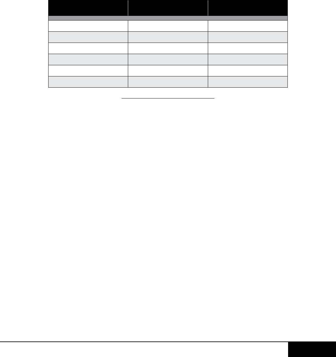
The PowerEdge T610 system supports the following 2D graphics video modes:
SECTION 14. AUDIO
A. Overview / Description
No speakers supported.
Table: PowerEdge T610 Video Modes
RESOLUTION REFRESH RATE (HZ) COLOR DEPTH (BIT)
640 x 480 60, 72, 75, and 85 8, 16, and 32
800 x 600 56, 60, 72, 75, and 85 8, 16, and 32
1024 x 768 60, 72, 75, and 85 8, 16, and 32
1152 x 864 75 8, 16, and 32
1280 x 1024 60, 75, and 85 8 and 16
1280 x 1024 60 32
SECTION 15. RACK INFORMATION
A. Overview / Description
Rack installation components such as rails are provided with the PowerEdge T610 Rack Kit. The rack
installation components are as follows: Sliding Rack mount with latest generation Cable Management
Arm (CMA). The PowerEdge T610 will feature slam latches to oer easier removal from the rack.
When the system is installed in a rack, please observe the following guidelines:
•Nothingshouldbelocatedwithin12"ofthefrontoftheunitthatwouldrestricttheairowinto
the system.
•Nothingshouldbemountedorplacedbehindthechassisthatwouldrestrictairowfrom
exiting the system. Only Dell approved CMAs can be placed behind the chassis. All other
objects should be located at least 24" away from the rear of the chassis.
When 2 systems are placed back to back, the separation between the units should be at least 24" if the
exit airflow is equivalent for the two chassis. This will allow the exit air to escape without creating an
extreme back pressure at the rear of one of the chassis.


